Optical-fiber junction protector

An optical fiber splicing and protector technology, which is applied to the coupling of optical waveguides, fiber mechanical structure, etc., can solve the problems of time-consuming construction, inconvenient construction, and fiber splicing point breakage, etc., and achieves simple construction and installation. 、Double protection with obvious effect of pull-off force

Active Publication Date: 2013-11-27
NANJING HUAMAI TECH +1
View PDF6 Cites 3 Cited by
  • Summary
  • Abstract
  • Description
  • Claims
  • Application Information

AI Technical Summary

Problems solved by technology

The fixed structure of the end clamping the fiber makes it easy to pull out the fiber and cause the splicing po

Method used


Image

  • Optical-fiber junction protector
  • Optical-fiber junction protector
  • Optical-fiber junction protector

Examples


Embodiment 1

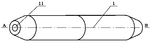
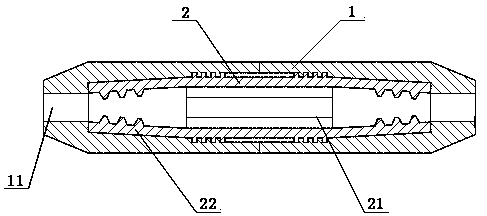
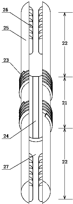
[0027] like figure 1 , figure 2 As shown, an optical fiber splice protector includes an inner shell 2 and an outer shell 1 . The structure of the inner shell 2 is as figure 2 , image 3 As shown, it is in the shape of a cylinder, including a main body 21 and a clip body 22 . The main body 21 is provided with a groove 24 along the axial direction. The groove 24 makes the main body 21 have a C-shaped cross section. Both ends of the main body 21 are respectively provided with two sets of external threads 23 . There are two clip bodies 22, which are respectively located at two ends of the main body. The clip body 22 is composed of two clip pieces 25 . One end of the clip 25 is fixed on the main body 21 . The main body 21 and the clip body 22 are an integral structure. The clip chamber 27 and the groove 24 between the two clips 25 constitute a continuous protection chamber. There are two outer shells 1, which are sleeved outside the inner shell 2. The structure of shel...

Embodiment 2

[0032] Referring to Example 1, on the basis of Example 1, this example further adds a C-shaped collar 3, such as Figure 5 shown. The structure of the C-type collar 3 is as Image 6 As shown, a C-shaped ring piece 31 and a pressure blocking piece 32 are included. The blocking piece 32 is arranged on both sides of the C-shaped ring piece 31 . like Figure 7 As shown, a C sleeve shaft 28 is provided between two sets of external threads 23 of the main body 21 of the inner shell 2 . After the installation is completed, the C-shaped collar 3 is sleeved on the outside of the C sleeve shaft 28. The blocking piece 32 is stuck between the outer shell 1 and the inner shell 2 . There is a gap between the outer shell 1 and the inner shell 2 at the C sleeve shaft 31 . The pressure blocking sheet 32 ​​is stuck in the gap. The C-shaped ring sheet 31 of the C-shaped collar 3 is sandwiched between the two shells 1, such as Figure 5 shown. Compared with embodiment 1, in embodiment 1, ...


PUM


Abstract

The invention discloses an optical-fiber junction protector. The optical-fiber junction protector comprises an inner shell, outer shells and a C-shaped lantern ring. The inner shell is of a cylinder shape and comprises a main body and clamping bodies. A groove is formed in the main body in the axial direction. Two external threads are arranged at the two ends of the main body respectively. A C-shaped sleeve is arranged between the two external threads. The number of the clamping bodies is two, wherein the clamping bodies are located at the two ends of the main body and comprise two clamping pieces. Each clamping piece is provided with a tooth-shaped body. A clamping cavity between the clamping pieces and the groove of the main body form a junction protection cavity. The number of the outer shells is two, and the inner shell is sleeved with the outer shells. Each outer shell is of a cylinder structure, wherein one end of the outer shell is a thread opening, and the other end of the outer shell is an optical fiber opening. The C-shaped lantern ring comprises a C-shaped ring piece and blocking compression pieces arranged on the two sides of the C-shaped ring piece. The C-shaped sleeve is sleeved with the C-shaped lantern ring. The blocking compression pieces are clamped between the outer shells and the inner shell. The C-shaped ring piece is clamped between the two outer shells. The C-shaped lantern ring and the inner shell are both made of transparent materials. The optical-fiber junction protector is convenient to construct, greatly increases the pulling-out force index, and enables the state of an optical fiber at a junction to be seen.

Description

technical field [0001] The invention relates to a protection device which is sheathed outside the optical fiber after the optical fiber is spliced. Background technique [0002] With the development of optical digital communication technology and the in-depth application of optical fiber technology, fiber-to-the-home and fiber-to-the-desktop have become a trend. In the context of this application, the use of optical fibers cannot avoid breaking. After the fiber is broken, it can be spliced ​​by heat fusion. The fiber connection part needs special protection, otherwise it is easy to break again or cracks appear at the connection point, which will seriously attenuate the optical signal and affect communication. The current optical fiber splicing protector generally adopts a fixed structure in which the tail end is clamped with spun fiber, and is similar to a penetrating placement mode of a needle. The fixed structure of the end clamping the spun fiber makes it easy for the ...

Claims


Application Information

Patent Timeline
IPC IPC(8): G02B6/38G02B6/44
Inventor 姜涛朱孟达顾胜波
Owner NANJING HUAMAI TECH
Why Eureka
Try Eureka