Dustproof cover of shock absorber

A technology of dust cover and shock absorber, applied in the direction of shock absorber, spring/shock absorber, shock absorber, etc.

Inactive Publication Date: 2012-07-11
成都九鼎科技(集团)有限公司
View PDF4 Cites 1 Cited by
  • Summary
  • Abstract
  • Description
  • Claims
  • Application Information

AI Technical Summary

Problems solved by technology

[0003] The invention purpose of the present invention is to provide a kind of shock absorber dust cover, to solve the above problems that the existing shock absorber dust cover exists during friction welding

Method used


Image

  • Dustproof cover of shock absorber
  • Dustproof cover of shock absorber
  • Dustproof cover of shock absorber

Examples


Embodiment 1

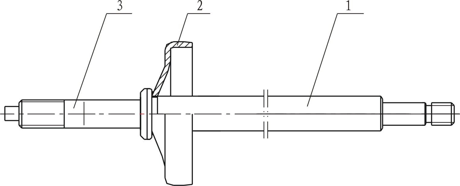
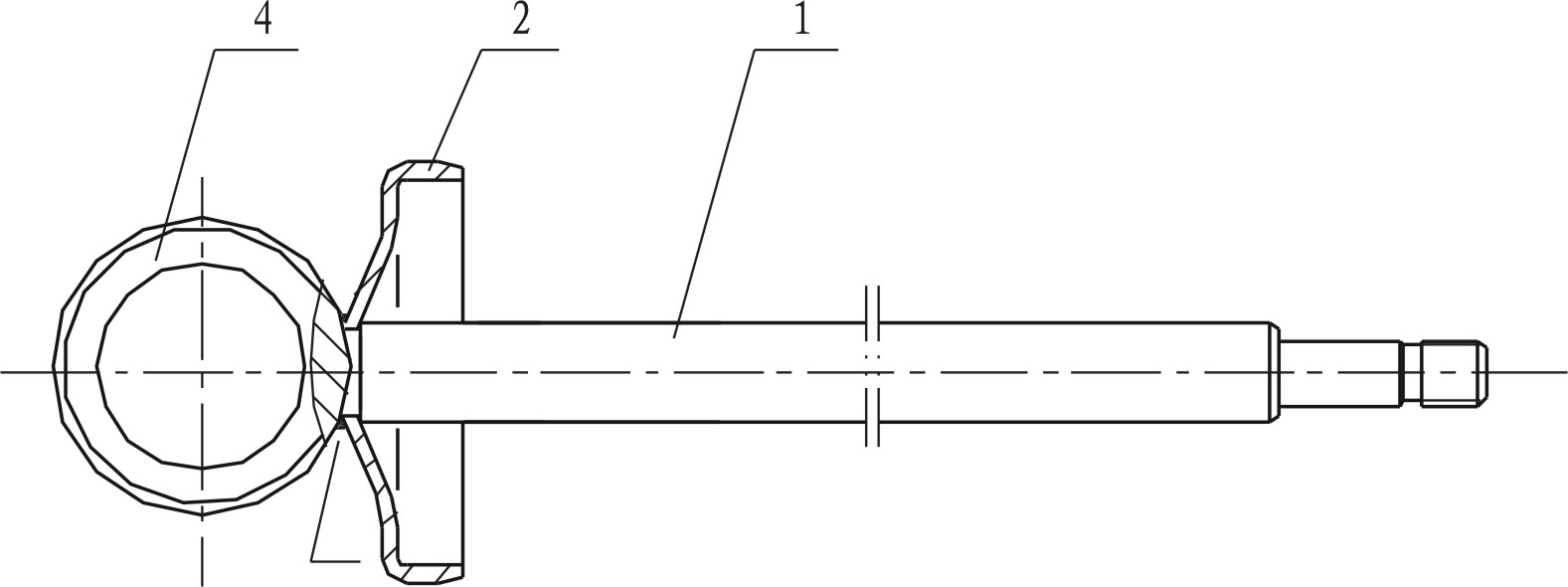
[0022] like Figure 5 The shock absorber dust cover 2 shown has a circular welding opening 21 in the center of the top, and the cover body at the circular welding opening 21 is upward in the axial direction, and then extends radially outward to form a curling edge 22 .

[0023] In order to keep the dust cover 2 coaxial with the connecting rod 1 better, the inner diameter of the bead 22 is designed to be the same as the inner diameter of the welding port 21 .

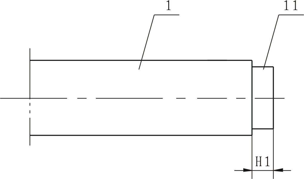
[0024] In order to better participate in the friction welding of the shock absorber dust cover 2 and better maintain coaxiality with the connecting rod 1, the upper end surface 24 of the bead 22 is an annular plane perpendicular to the axis of the shock absorber dust cover 2 , the diameter of the step 11 is the same as the inner diameter of the bead 22 .

[0025] The inner wall of the curling 22 and the welding port 21 forms an inner facade 23. In order to prevent welding slag from accumulating in the curling, affectin...

Embodiment 2

[0030] like Figure 5 As shown, the structure of the shock absorber dust cover 2 is the same as the first embodiment. The outer diameter of the curling 22 is 16±0.1mm, the inner diameter is 10.5+0.10mm, the thickness is 2.10-0.1mm, and the height H2 of the inner facade is 3.60-0.1mm.

[0031] Welding parameters:

[0032]

Embodiment 3

[0034] like Figure 5 As shown, the structure of the shock absorber dust cover 2 is the same as that of the first embodiment. The outer diameter of the curling 22 is 20±0.1mm, the inner diameter is 14.5+0.10mm, the thickness is 2.10-0.1mm, and the height H2 of the inner facade is 3.60-0.1mm.

[0035] Welding parameters:

[0036]

[0037] Effects and advantages and disadvantages:

[0038]

[0039] To sum up, after the improved dust cover is put on the step of the end face of the connecting rod, the junction of the inner elevation and the upper end face of the curling is at right angles, so as to avoid the accumulation of welding slag in the curling, and the connection between the connecting rod and the joint or the lifting ring and A part of the beading on the dust cover (the third part of the beading in the height of the inner facade) participates in welding at the same time, and is assembled into an assembly through rotational friction welding, so that the three parts...


PUM


Abstract

The invention discloses a dustproof cover of a shock absorber. A circular welding joint is arranged at the center of the top of the dustproof cover, and a cover body at the circular welding joint axially extends upwards and then radially extends outwards to form a turned edge. The inner diameter of the turned edge is as same as that of the welding joint, and the upper end face of the turned edge is an annular plane perpendicular to the axis of the dustproof cover of the shock absorber. The inner walls of the turned edge and the welding joint form an inner vertical face, and a right angle is formed at the junction of the inner vertical face and the upper end face. The height of the inner vertical face is equal to that of a step of a connecting rod. After the improved dustproof cover is sleeved on the step on the end face of the connecting rod, the right angle is formed at the junction of the inner vertical face and the upper end face of the turned edge, welding slag is prevented from being accumulated in the turned edge, the connecting rod, a connector or hanging ring and part of the turned edge of the dustproof cover (one third of the height of the inner vertical face close to the turned edge) are simultaneously involved in welding, welded into a component by means of rotary friction and become rigid parts, loosening of the dustproof cover is prevented, and breakaway force and qualification rate are greatly increased.

Description

technical field [0001] The invention relates to the technical field of shock absorbers, in particular to a shock absorber dust cover. Background technique [0002] In the structure of the shock absorber, the welding assembly of the connecting rod adopts the structure of friction welding, the structure is as follows figure 1 , 2 shown. Welding requirements: joint 3 or lifting ring 4 and connecting rod 1 need to ensure a certain welding tension after friction welding; dust cover 2 and joint 3 or lifting ring 4 and connecting rod 1 are not loose after welding. Existing dust cap 2 (see image 3 ) into the connecting rod (see Figure 4 ) after the step 11 on the end face, the welding slag generated when the connecting rod 1 is welded with the joint 3 or the lifting ring 4 accumulates and fixes the dust cover 2, and the loosening of the dust cover is prohibited, but the welding port 21 is relatively thin and does not participate in welding. Therefore, the amount of welding sl...

Claims


Application Information

Patent Timeline
Patent Type & Authority Applications(China)
IPC IPC(8): F16F9/36
Inventor 邢希秋严茂
Owner 成都九鼎科技(集团)有限公司
Why Eureka
Try Eureka