
Manufacturing method of hollow ring member

The technology of a ring member and manufacturing method, which is applied in the field of manufacturing, can solve problems such as large welding deformation, and achieve the effects of reducing welding deformation, avoiding internal stress, and increasing rigidity

Active Publication Date: 2015-08-12
SHANDONG NUCLEAR POWER EQUIP MFG
View PDF6 Cites 0 Cited by
  • Summary
  • Abstract
  • Description
  • Claims
  • Application Information

AI Technical Summary

Problems solved by technology

[0003] The present invention aims at the technical problem of excessive welding deformation in the manufacture of existing hollow ring members, and provides a method for manufacturing hollow ring members with small welding deformation

Method used


Image

  • Manufacturing method of hollow ring member
  • Manufacturing method of hollow ring member
  • Manufacturing method of hollow ring member

Examples


Embodiment Construction

[0026] Now, specific embodiments of the present invention will be described in detail with reference to the accompanying drawings.

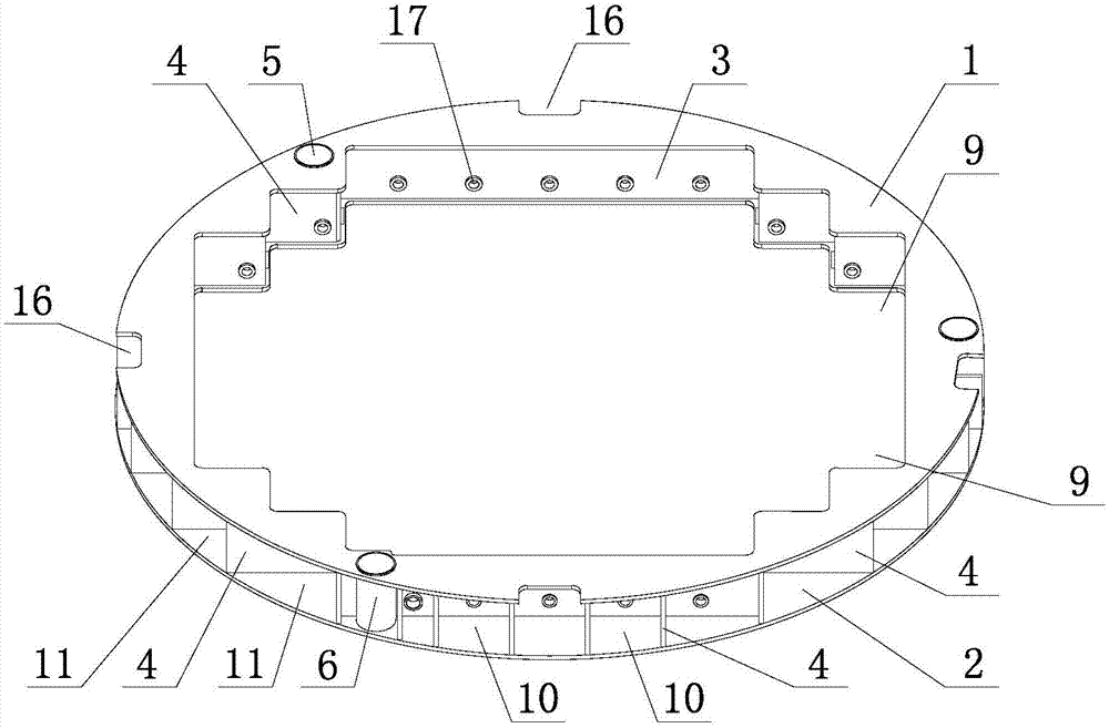
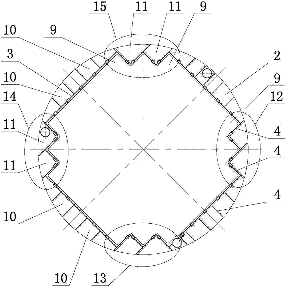
[0027] Such as figure 1 and figure 2 The hollow annular member shown has a top plate 1 and a bottom plate 2, the top plate 1 and the bottom plate 2 are basically the same in structure, and both are disc-shaped. They are parallel to each other and the top plate 1 is located directly above the bottom plate 2 , the difference is that the top plate 1 is uniformly provided with four notches 16 along its circumference.

[0028] In the middle of the top plate 1 and the bottom plate 2, an inner panel 3 and a reinforcing plate 4 are vertically provided. There are four inner panels 3, which are evenly distributed along the circumference of the top plate 1 and the bottom plate 2; the reinforcing plate 4 is used to fix the top plate 1 , Base plate 2 and inner panel 3. Threaded sleeves 17 are provided on the inner panel 3 and part of the reinforcing plate...


PUM

PropertyMeasurementUnit
diameteraaaaaaaaaa

Abstract

The invention provides a manufacturing method of a hollow annular element, and solves the technical problem of large welding deformation of the conventional hollow annular element. The manufacturing method mainly comprises the following steps of (1) blanking each part for forming the hollow annular element and precisely controlling the size of each part; (2) compressing a soleplate on a horizontal platform by utilizing a simple tool, and assembling each part to an integral member; and (3) welding the assembled hollow annular element through a subarea symmetrical welding method, a backward welding method, a skip welding method and the like. The manufacturing method can be applied to the fields of nuclear power plant and manufacturing of similar members.

Description

technical field [0001] The invention relates to a manufacturing method, in particular to a manufacturing method of a hollow ring member with small welding deformation. Background technique [0002] The existing hollow annular member is installed inside the circular cylinder as an inner part, and there is an inner cavity in the middle, and the inner cavity accommodates other inner parts to pass through, and it is necessary to control the diameter of the outer circle and the size and shape of the inner cavity; figure 1 There will be a lifting rod passing through the circular hole 5 of the hollow ring member shown, so its position also needs to be strictly controlled. The size of each part forming the hollow annular member is relatively small relative to the diameter of the entire hollow annular member, and the rigidity of the entire member is also small, which results in a large welding deformation. Therefore, it is necessary to formulate reasonable and reliable blanking, ass...

Claims


Application Information

Patent Timeline
Patent Type & Authority Patents(China)
IPC IPC(8): B23K9/173B23K37/04
Inventor 刘山厉福海王国彪杨中伟刘茂平胡永清曹中云丁连征赵海丽侯继民林法振班勇
Owner SHANDONG NUCLEAR POWER EQUIP MFG
Learn More