Three-way catalyst with flow rectifier

A three-way catalytic converter and catalytic converter technology, applied in the direction of mufflers, exhaust devices, engine components, etc., can solve the problems of being unable to apply to engine working conditions, affecting engine power, and increasing exhaust back pressure, etc., to improve conversion Efficiency and utilization, long service life, reducing the effect of structural changes

Active Publication Date: 2013-12-04
AUTOMOBILE RES INST OF TSINGHUA UNIV IN SUZHOU XIANGCHENG
View PDF4 Cites 4 Cited by
  • Summary
  • Abstract
  • Description
  • Claims
  • Application Information

AI Technical Summary

Problems solved by technology

However, these structures are fixed and cannot be applied to different engine operating conditions
Under certain working conditions, it will cause a decline in uniformity and a substantial increase in exhaust back pressure, affecting engine power

Method used


Image

  • Three-way catalyst with flow rectifier
  • Three-way catalyst with flow rectifier
  • Three-way catalyst with flow rectifier

Examples


Embodiment Construction

[0022] The present invention will be further described below in conjunction with the accompanying drawings.

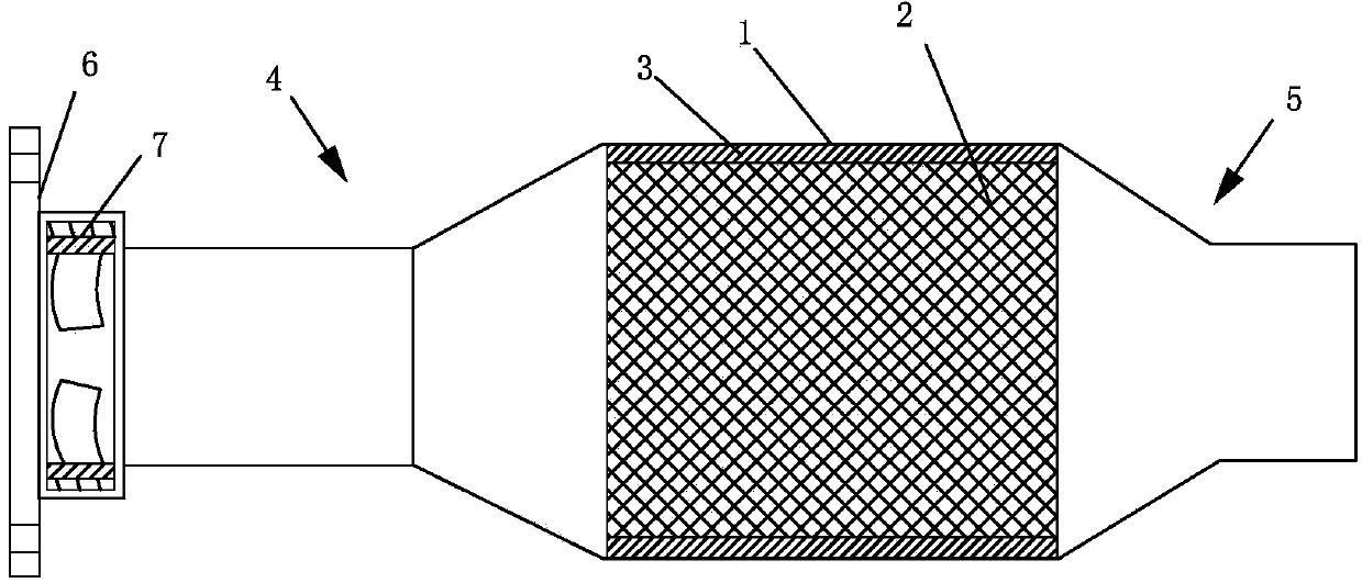
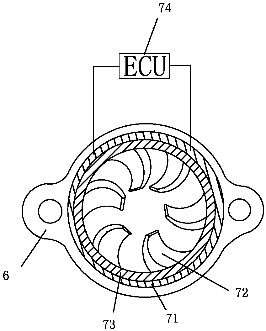
[0023] as attached Figure 1~4 The shown three-way catalytic converter with a flow equalizer includes a housing 1, a catalyst carrier 2, a liner 3, an air intake passage 4 connected to one end of the housing 1, and an exhaust gas connected to the other end of the housing 1. The channel 5 and the catalytic converter flange 6 connected with the intake channel 4 are provided with a flow equalizing device 7 inside the catalytic converter flange 6 and the flow equalizing device 7 is located at the air inlet of the intake channel 4 .

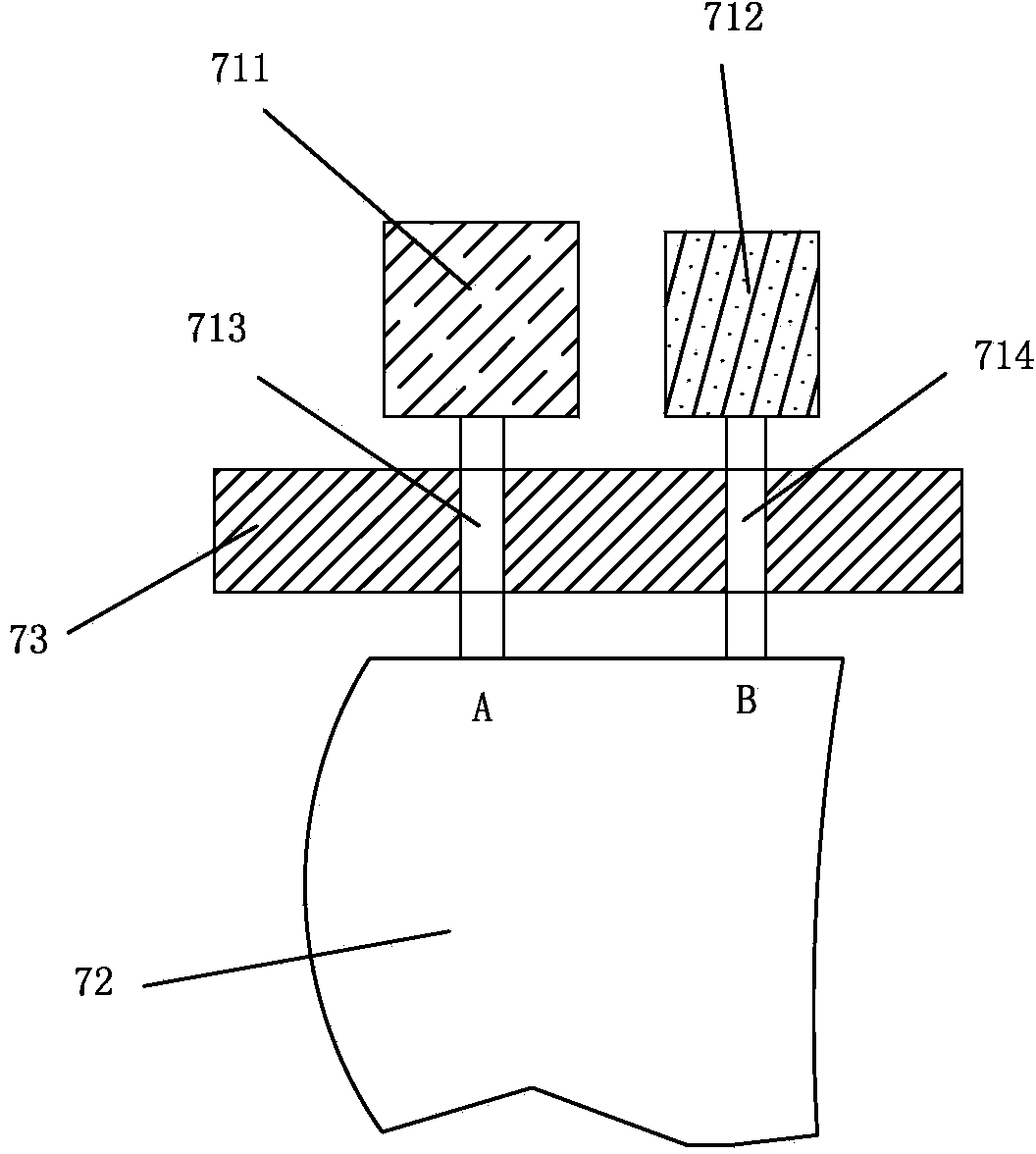
[0024] The current equalizing device 7 includes an electromagnetic ring device 71 coaxially arranged with the catalyst flange 6, an electronic control unit 74 connected to the electromagnetic ring device 71 and used to control the work of the electromagnetic ring device 71, arranged along the circumference of the electromagnetic ring device 71...


PUM


Abstract

The invention relates to a three-way catalyst with a flow rectifier. The three-way catalyst comprises a shell, a catalyst carrier, a liner, an inlet passage and an exhaust passage, wherein the inlet passage is connected with one end of the shell, and the exhaust passage is connected with the other end of the shell. The three-way catalyst also comprises a catalyst flange. The catalyst flange is connected with the inlet passage; the flow rectifier is arranged in the catalyst flange and is located in the air inlet of the inlet passage. The flow rectifier comprises an electromagnetic ring device, an electronic control unit and a plurality of blades, wherein the electromagnetic ring device is coaxial with the catalyst flange; the electronic control unit is connected with the electromagnetic ring device and is used for controlling the electromagnetic ring device to work; the blades are arranged along the circumferential direction of the electromagnetic ring device and are controlled by the electromagnetic ring device to rotate; each blade is connected with the electromagnetic ring device by a connecting rod. According to the three-way catalyst provided by the invention, the blades can be changed within a certain rotation angle range, and are completely matched with all instantaneous conditions of an engine, and therefore, the conversion efficiency and the use ratio of the three-way catalyst are effectively improved, and moreover, maximum effective power is output by the engine.

Description

technical field [0001] The invention relates to a three-way catalytic converter with a flow equalizing device, which belongs to the field of engine emission pollution control. Background technique [0002] The three-way catalytic converter plays a vital role in automobile exhaust emissions. It can effectively promote the secondary reaction of toxic and harmful gases generated during the combustion process, and convert them into non-toxic gases and discharge them into the atmosphere. With the continuous improvement of emission laws and regulations, improving the efficiency and prolonging the service life of the three-way catalytic converter has become the focus of research at this stage. Among them, the internal flow uniformity of the three-way catalytic converter is one of the important indicators to measure the effectiveness of the three-way catalytic converter. . In the existing three-way catalytic converter, due to structural factors, when the exhaust gas flows through t...

Claims


Application Information

Patent Timeline
Patent Type & Authority Applications(China)
IPC IPC(8): F01N3/28F01N13/08
Inventor 郑四发韩强
Owner AUTOMOBILE RES INST OF TSINGHUA UNIV IN SUZHOU XIANGCHENG
Why Eureka
Try Eureka