

Electromagnetic actuator
An electromagnetic actuator, permanent magnet technology, applied in the direction of electromagnets, electromagnets with armatures, circuits, etc., can solve problems such as increased weight of moving components
- Summary
- Abstract
- Description
- Claims
- Application Information
AI Technical Summary
Problems solved by technology
Method used
Image

Examples
no. 1 example
[0037] According to the first embodiment, the electromagnetic actuator is applied to the valve lift adjustment device that adjusts the lift amount of the intake valve of the internal combustion engine.
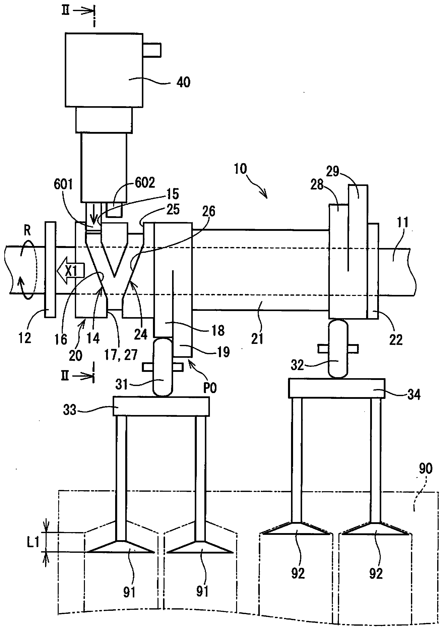
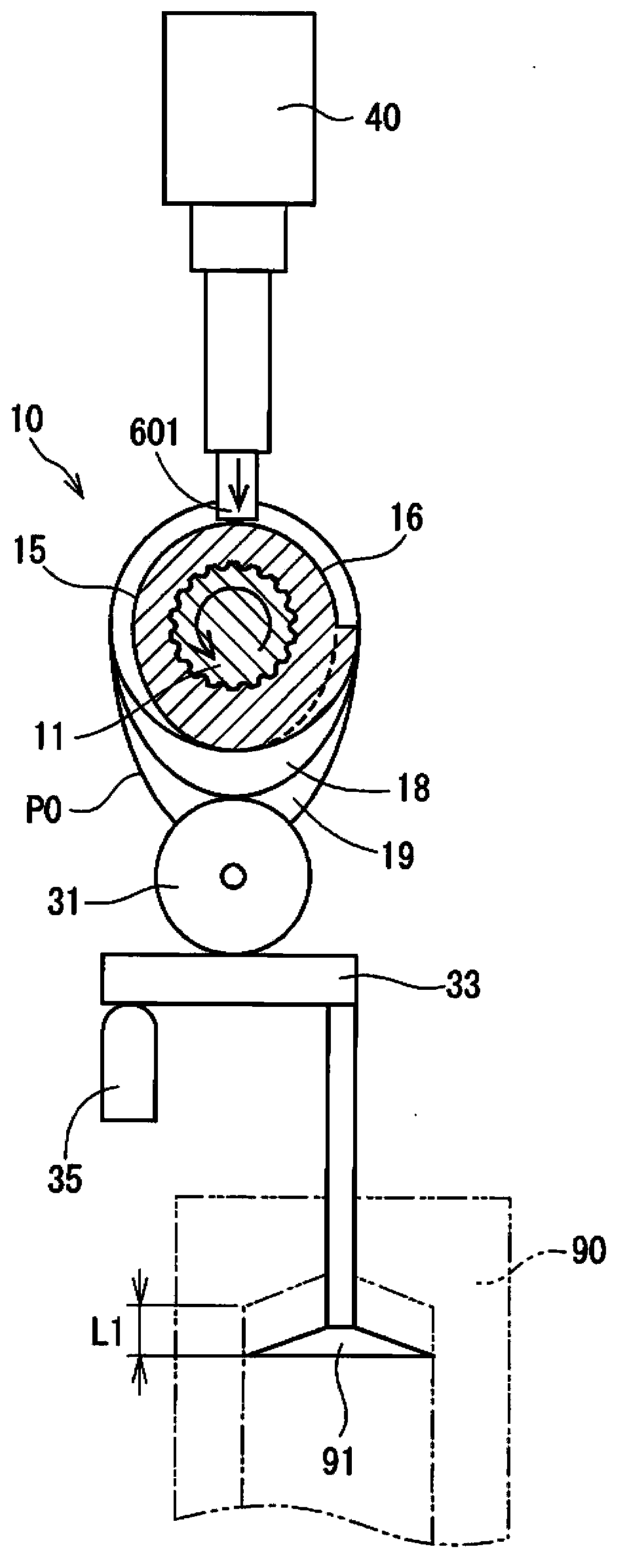
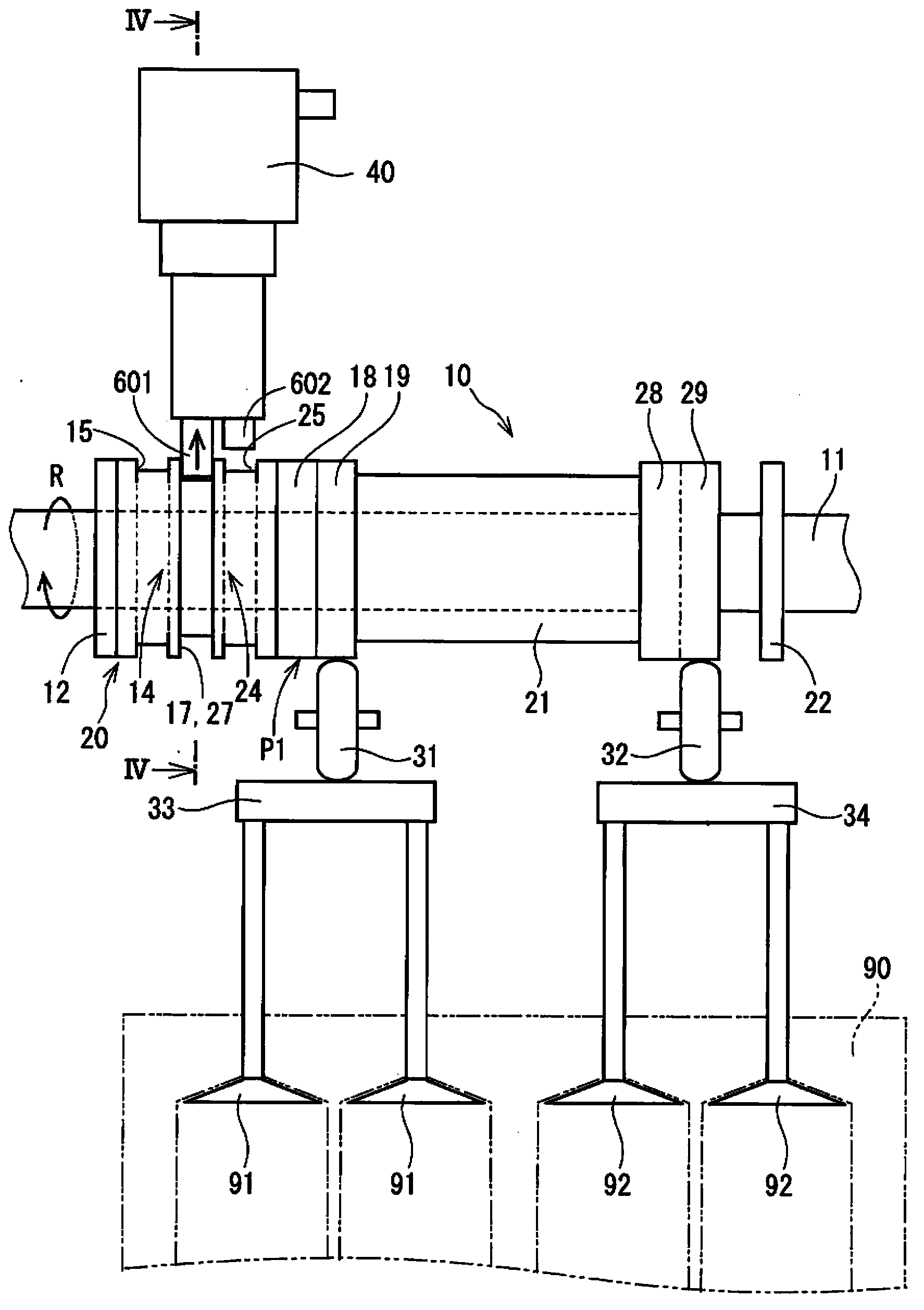
[0038] refer to Figures 1 to 6 , the structure of the valve lift adjustment device will be described below. The valve lift adjusting device 10 adjusts the lift amounts of the intake valves 91 , 92 by a cam provided to a slider 21 that rotates with the camshaft 11 . The intake valves 91 , 92 are linked to each other via rollers 31 , 32 and rocker arms 33 , 34 .
[0039] The camshaft 11 is connected to the crankshaft in such a way that they rotate together. Camshaft 11 rotates in direction "R", as figure 1 shown in . Such as figure 2 , 4 As shown in and 6, the camshaft 11 has splined external teeth, and the slider 21 engages with the splined external teeth. The slider 21 rotates together with the camshaft 11 and moves axially relative to the camshaft 11 . That is, the ...
no. 2 example
[0111] refer to Figures 14 to 16 , hereinafter, a second embodiment of the electromagnetic actuator will be described. In each of the following embodiments, parts and components that are substantially the same as those in the first embodiment are denoted by the same reference numerals, and the same description will not be repeated.
[0112] Such as Figure 14 and 15 As shown in , the electromagnetic actuator 405 of the second embodiment has an integrated permanent magnet 54 , adapters 555 , 556 and an electrode holder 85 . The structure of these elements is different from that of the first embodiment. The integrated permanent magnet 54, adapters 555, 556, and electrode holder 85 are formed symmetrically with respect to a virtual plane "V" including a pin axis "O1" and a pin axis "O2".
[0113] The integral permanent magnet 54 is a column whose cross-sectional shape is an ellipse. The integral permanent magnet 54 is fixed to the electrode holder 85 in such a way that its ...
no. 3 example
[0126] refer to Figures 17 to 20 , hereinafter, a third embodiment of the electromagnetic actuator will be described.
[0127] Such as Figure 17 and 18 As shown in , the valve lift adjustment device 10 has two switching parts 13 , 23 , and electromagnetic actuators 407 , 408 are applied to the valve lift adjustment device 10 . The first switching portion 13 has a first engaging groove 14 , and the second switching portion 23 has a second engaging groove 24 .
[0128] Electromagnetic actuators 407, 408 have control pins 607, 608, respectively. The first electromagnetic actuator 407 corresponding to the first switching portion 13 advances the control pin 607 in synchronization with the rotation of the camshaft 11, so that the control pin 607 engages with the first engagement groove 14, as Figure 17 shown in . The second electromagnetic actuator 408 corresponding to the second switching portion 23 advances the control pin 608 in synchronization with the rotation of the ca...
PUM
 Abstract
Description
Claims
Application Information