Magnetic steel pushing-in device

A technology of propulsion device and magnetic steel, which is applied in the manufacture of stator/rotor body, etc., can solve the problems of low efficiency, time-consuming, cumbersome methods, etc., and achieve the effect of improving work efficiency and efficient installation

Active Publication Date: 2013-12-04
XINJIANG GOLDWIND SCI & TECH
View PDF7 Cites 8 Cited by
  • Summary
  • Abstract
  • Description
  • Claims
  • Application Information

AI Technical Summary

Problems solved by technology

[0003] The above method is cumbersome and may need to be heated during

Method used


Image

  • Magnetic steel pushing-in device
  • Magnetic steel pushing-in device
  • Magnetic steel pushing-in device

Examples


Embodiment Construction

[0022] In order to enable those skilled in the art to better understand the present invention, specific embodiments of the present invention will be described in detail below in conjunction with the accompanying drawings.

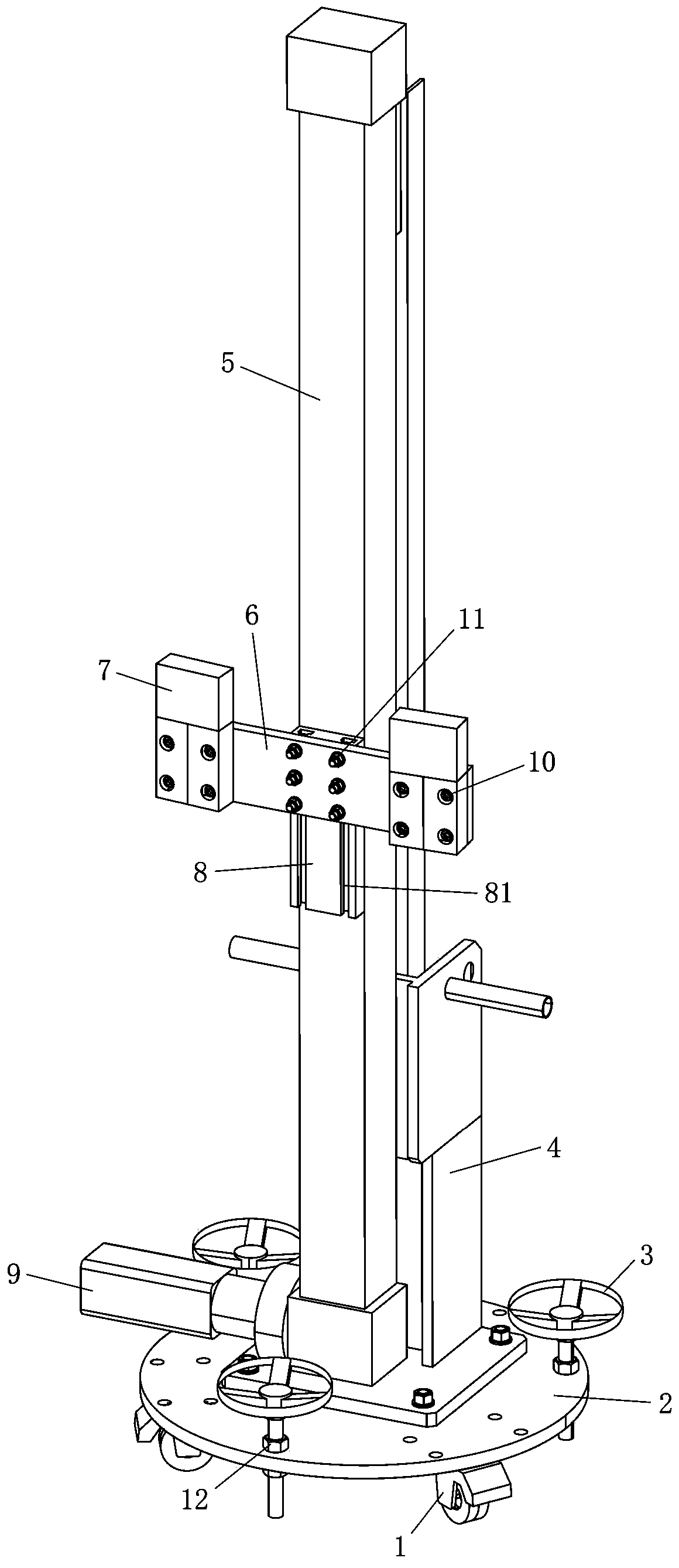
[0023] refer to figure 1 , figure 1 is a structural schematic diagram of a magnetic steel pushing device according to an embodiment of the present invention.

[0024] According to an embodiment of the present invention, a magnet steel pushing device for installing a magnet on a yoke is provided. Several rows of cavities are formed on the cylindrical yoke vertically or at a small inclination angle to the vertical direction, the size of the cavities can ensure that the magnetic steel is smoothly pushed into it from bottom to top And the magnets are stuck in the cavity without moving in the circumferential direction, that is, the magnets in the cavity only have the freedom of moving up and down, and the number of magnets pushed into the cavity depends on the...


PUM


Abstract

The invention discloses a magnetic steel pushing-in device which is used for installing magnetic steel into a cavity on a magnet yoke. The magnetic steel pushing-in device comprises a base, linear units, a pushing device and a driving device. The linear units are vertically fixed to the base. The pushing device can move vertically relative to the magnet yoke through matching with the linear units so as to push the magnetic steel into the cavity. The driving device is used for driving the pushing device to move vertically. The pushing device can push the magnetic steel into a preset position in the cavity on the magnet yoke through interaction of the pushing device and the linear units. By means of the magnetic steel pushing-in device, installation of the magnetic steel can be conveniently and efficiently completed, and work efficiency is significantly improved.

Description

technical field [0001] The invention relates to the field of generators, in particular, the invention relates to a magnetic steel pushing device for installing the magnetic steel on a magnetic yoke. Background technique [0002] In terms of the installation of magnets for large-scale wind turbines, the magnets are often fixed on the yoke by means of installation molds and bonding. Specifically, firstly, the installation mold is accurately hung on the yoke, and a cavity for curing the bonded magnetic steel is formed between the installation mold and the yoke; then the magnetic steel is pushed into the cavity by means of a linear unit; finally The glue injection process is carried out between the magnetic steel and the yoke to fix the magnetic steel, and then the installation mold is withdrawn. [0003] The above method is cumbersome, and heating may be required during the glue injection process, which takes a long time and is not efficient. Therefore, it is necessary to pro...

Claims


Application Information

Patent Timeline
IPC IPC(8): H02K15/03
Inventor 王生旭詹军
Owner XINJIANG GOLDWIND SCI & TECH
Why Eureka
Try Eureka