Chain cutter

A technology for cutting chains and chain pins, which is applied in the field of chain cutters, and can solve problems such as scrapping the chain, affecting the normal rotation of the chain, and preventing the chain pin from being pushed in horizontally.

Active Publication Date: 2013-12-11
SUZHOU CHANGSHENG ELECTROMECHANICAL
View PDF7 Cites 3 Cited by
  • Summary
  • Abstract
  • Description
  • Claims
  • Application Information

AI Technical Summary

Problems solved by technology

[0002] The traditional chain cutter includes a base and a chain positioning tooth and a screw ejector rod arranged horizontally on the base, but there is no structure to fix the chain pin, and when the chain is ...

Method used


Image

  • Chain cutter
  • Chain cutter
  • Chain cutter

Examples


Embodiment Construction

[0013] The preferred technical solutions of the present invention will be described in detail below in conjunction with the accompanying drawings.

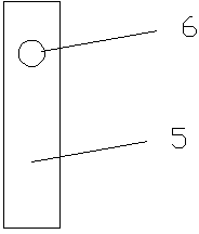
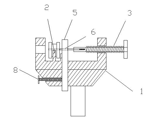
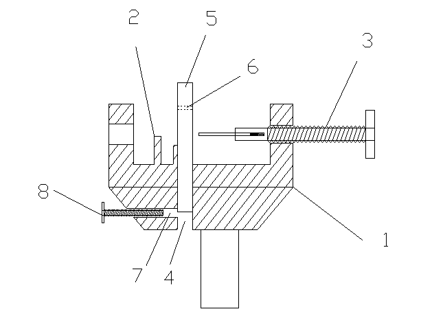
[0014] Such as figure 1 As shown, the chain cutter of the present invention includes a base 1 and a chain positioning tooth 2 and a screw jack 3 horizontally arranged on the base 1, and the base close to the side of the positioning tooth 2 facing the screw jack 3 1, a chute 4 is provided downwards, the axial direction of the chute 4 is perpendicular to the axial direction of the screw jack 3, and a sliding block 5 for fixing the chain pin is arranged in the chute 4, on the sliding block 5 A chain pin fixing hole 6 is provided throughout, the axial direction of the chain pin fixing hole 6 is consistent with the horizontal movement direction of the thimble of the screw ejector rod 3, and a screw hole 7 communicating with the chute 4 is horizontally provided on the base 1, and the screw hole 7 communicates with the chute 4. The hole...


PUM


Abstract

The invention discloses a chain cutter. The chain cutter comprises a base, a chain positioning tooth and a spiral ejector rod, wherein the chain positioning tooth and the spiral ejector rod are arranged on the base; a sliding chute is formed in a position, close to one side where the positioning tooth faces the spiral ejector rod, of the base in a downward penetrating mode; the axial direction of the sliding chute is vertical to that of the spiral ejector rod, a sliding block used for fixing a chain pin is arranged in the sliding chute and provided with a chain pin fixing hole in a penetrating mode, and the axial direction of the chain pin fixing hole is identical with the horizontal moving direction of an ejector pin of the ejector rod; a threaded rod hole communicated with the sliding chute is horizontally formed in the base, and a threaded rod used for fixing the sliding block is arranged in the threaded rod hole. Compared with the prior art, the chain cutter has the advantages that the position of the sliding block is adjusted and fixed through the threaded rod, and the chain pin is fixed through the chain pin fixing hole in the sliding block, so the chain pin can be horizontally pushed into a chain when the chain pin is connected with the chain, and the chain cutter is convenient to use and practical and cannot damage the chain.

Description

technical field [0001] The invention relates to a chain cutter. Background technique [0002] The traditional chain cutter includes a base and a chain positioning tooth and a screw ejector rod arranged horizontally on the base, but there is no structure to fix the chain pin, and when the chain is connected, the chain pin cannot be pushed into the chain horizontally If it is light, it will affect the normal rotation of the chain, and if it is serious, the chain link will be bent and the chain will be scrapped. Contents of the invention [0003] The technical problem to be solved by the present invention is to provide a chain cutter capable of horizontally pushing the chain pin into the chain in view of the above-mentioned deficiencies in the prior art. [0004] In order to solve the problems of the technologies described above, the technical solution adopted in the present invention is: [0005] A chain cutter, comprising a base, a chain positioning tooth and a screw ejec...

Claims


Application Information

Patent Timeline
IPC IPC(8): B21L21/00
Inventor 张学平朱忠海
Owner SUZHOU CHANGSHENG ELECTROMECHANICAL
Why Eureka
Try Eureka