Spring tow hook

A technology of towing hooks and spring racks, applied in the direction of traction connectors, transportation and packaging, vehicle parts, etc., can solve the problems of heavy towing cables, inconvenient operation, damage, etc., and achieve the effect of convenient disassembly and reliable work

Inactive Publication Date: 2013-12-11
张晓荣
View PDF4 Cites 20 Cited by
  • Summary
  • Abstract
  • Description
  • Claims
  • Application Information

AI Technical Summary

Problems solved by technology

[0002] At present, tugboats, trailers, etc. will inevitably use tow hooks. According to different industry characteristics and needs, various types of tow hooks have been produced, but their function is only one, which is to pull objects to move, and must be in the process of moving. It cannot be unhooked, so producers and users make a big fuss about the strength and self-locking of the tow hook, so there will be a variety of tow hooks, but for the self-locking function, springs or reeds are added, and the self-locking function is powerful. When hooking, it is necessary to artificially overcome the elastic force of the spring or reed, and the dragging cable is heavy, which is very inconvenient to operate
[0003] In the case of using a tow hook, the objects to be towed must be relatively large or heavy. The main towed object needs to exert a large traction force on the towed object. At the moment when the traction force is applied to the object, due to the influence of the reaction force, the dragged object will receive a strong backward impact force. Under the action of the impact force, the mechanical parts will generate a large dynamic stress and may cause damage. , the hull or vehicle body may also be endangered

Method used


Image

  • Spring tow hook

Examples


Embodiment Construction

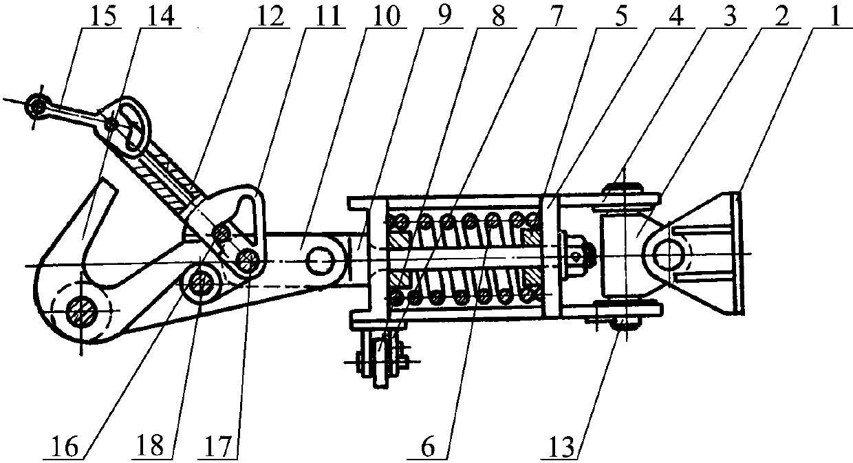
[0009] Such as figure 1 As shown, the present invention is a kind of spring tow hook, and it comprises tow hook 14, buffer device and joint 2, and eye plate 1 is connected on joint 2, and described joint 2 is cross joint; Described buffer device is made of spring frame 3, Spring pressing plate 4, spring 6 and spring axle core 9 are formed, and the bottom of described spring frame 3 is provided with roller bracket 7, and roller bracket 7 is provided with roller 8, and described spring pressing plate 4 is movably installed on spring frame 3 and can move along the spring. The pressing plate 4 moves axially, the spring 6 is located between the spring frame 3 and the spring pressing plate 4, the elastic two ends of the spring 6 are respectively provided with a spring seat 5, the spring shaft core 9 is located in the spring 6, and the spring shaft One end of the core 9 is fixedly connected with the spring pressing plate 4, and the other end extends out of the spring frame 3 and is c...


PUM


Abstract

The invention discloses a spring tow hook which comprises a tow hook body (14), a buffering device and a joint (2). The buffering device is composed of a spring rack (3), a spring pressing plate (4), a spring (6) and a spring central spindle (9), wherein the spring pressing plate (4) is movably mounted on the spring rack (3) and can move along the spring rack (3) in the axial direction, the spring (6) is located between the spring rack (3) and the spring pressing plate (4), the spring central spindle (9) is located in the spring (6), one end of the spring central spindle (9) is fixedly connected with the spring pressing plate (4), the other end of the spring central spindle (9) extends out of the spring rack (3) and is connected with the tow hook body (14), and the joint (2) is mounted on the spring rack (3) through a spring rack pin shaft (13). According to the spring tow hook, the reliable spring buffering measurement is used, the buffering spring is used for absorbing impact energy which is then converted to heat energy, and therefore the purpose that impact on mechanical equipment is reduced as much as possible is achieved.

Description

technical field [0001] The invention relates to a spring tow hook. Background technique [0002] At present, tugboats, trailers, etc. will inevitably use tow hooks. According to different industry characteristics and needs, various tow hooks have been produced, but it has only one function, which is to pull objects to move, and must be in the process of moving It cannot be unhooked, so producers and users make a big fuss about the strength and self-locking of the tow hook, so there will be a variety of tow hooks, but for the self-locking function, springs or reeds are added, and the self-locking function is powerful. Need artificially to overcome the elastic force of spring or reed when hooking, and dragging cable is heavy again, it is very inconvenient to operate. [0003] In the case of using a tow hook, the objects to be towed must be relatively large or heavy. The main towed object needs to exert a large traction force on the towed object. At the moment when the tracti...

Claims


Application Information

Patent Timeline
Patent Type & Authority Applications(China)
IPC IPC(8): B60D1/04B60D1/42B60D1/28
Inventor 张晓荣
Owner 张晓荣
Why Eureka
Try Eureka