Rotary compressor and refrigeration circulating device provided with rotary compressor

A rotary compressor and compression mechanism technology, applied in the field of compressors, can solve the problems of insufficient lubrication of moving parts, aggravated wear of compression mechanisms, and low energy efficiency of compressors, so as to achieve good energy efficiency, improve starting torque, and benefit Keep the effect

Active Publication Date: 2013-12-11
GUANGDONG MEIZHI COMPRESSOR
View PDF8 Cites 1 Cited by
  • Summary
  • Abstract
  • Description
  • Claims
  • Application Information

AI Technical Summary

Problems solved by technology

[0003] However, since the balance chamber is located below, the lubricating oil flowing out from the lubricating oil groove on the outer peripheral surface of the eccentric part will flow into the balance chamber, thereby deteriorating the starting torque of the compressor, and at the same time, too much oil in the balance chamber will cause the rest of the compression mechanism to move Components are not adequately lubricated, increasing compression mechanism wear
Moreover, the balance weight in the prior art has the phenomenon of secondary compression of the gas in the balance chamber, resulting in low energy efficiency of the compressor

Method used


Image

  • Rotary compressor and refrigeration circulating device provided with rotary compressor
  • Rotary compressor and refrigeration circulating device provided with rotary compressor
  • Rotary compressor and refrigeration circulating device provided with rotary compressor

Examples


Embodiment Construction

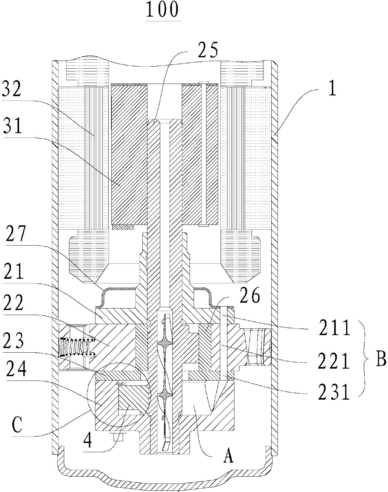
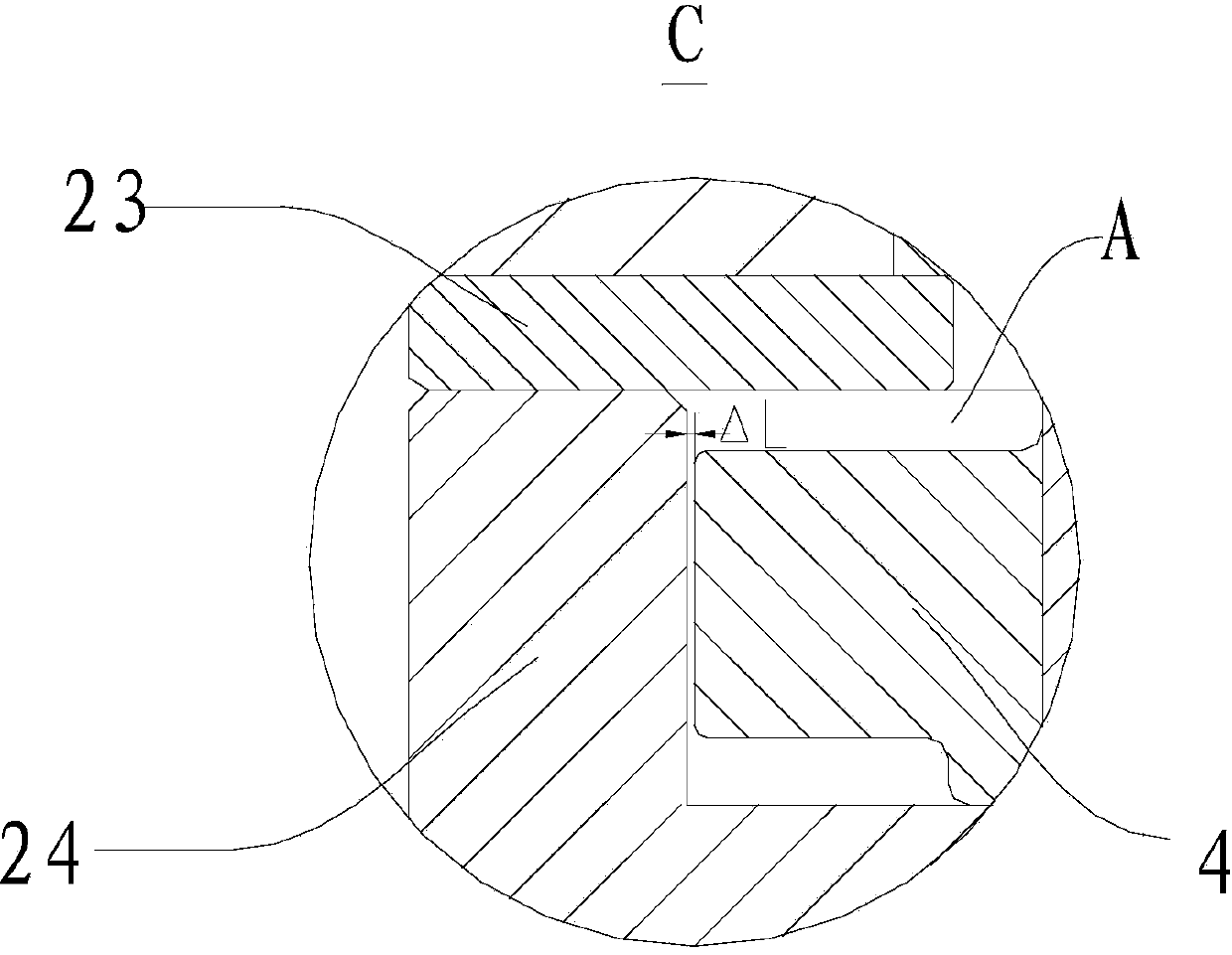
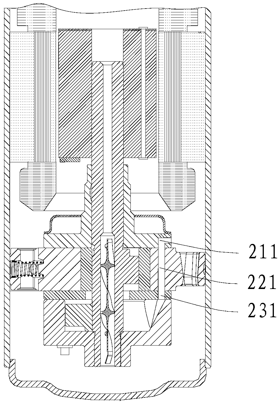
[0042] Embodiments of the present invention are described in detail below, examples of which are shown in the drawings, wherein the same or similar reference numerals designate the same or similar elements or elements having the same or similar functions throughout. The embodiments described below by referring to the figures are exemplary and are intended to explain the present invention and should not be construed as limiting the present invention.

[0043] In describing the present invention, it is to be understood that the terms "centre", "upper", "lower", "vertical", "horizontal", "top", "bottom", "inner", "outer" etc. indicate The orientation or positional relationship is based on the orientation or positional relationship shown in the drawings, and is only for the convenience of describing the present invention and simplifying the description, rather than indicating or implying that the referred device or element must have a specific orientation or be configured in a spec...


PUM


Abstract

The invention discloses a rotary compressor and a refrigeration circulating device provided with the rotary compressor. The rotary compressor comprises a shell, a compressing mechanism and a balance block, wherein the compressing mechanism is arranged inside the shell and comprises an air cylinder, a main bearing, an auxiliary bearing, a baffle plate and a crank shaft, the main bearing is arranged on the air cylinder, the baffle plate is arranged below the air cylinder, so that a compressing cavity is limited among the main bearing, the air cylinder and the baffle plate, the auxiliary bearing is arranged below the baffle plate, so that a balance cavity is limited between the auxiliary bearing and the baffle plate, the crank shaft is provided with an eccentric part, a lubrication oil groove is formed in the peripheral surface of the eccentric part, the lubrication oil groove and the bottom surface of the eccentric part are spaced from each other, the balance block is arranged on the crank shaft and located in the balance cavity, and the radial minimum distance between the balance block and the balance cavity is 0.2mm. The rotary compressor disclosed by the invention can effectively improve oil deposition phenomenon of the balance cavity, and meanwhile, the balance block can not carry out secondary compression on coolant in the balance cavity.

Description

technical field [0001] The invention relates to the field of compressors, in particular to a rotary compressor and a refrigeration cycle device with the rotary compressor. Background technique [0002] The traditional single-cylinder rotary compressor has an eccentric part, so during the rotation of the crankshaft, the eccentric part and the piston sleeved outside the eccentric part have a large centrifugal force when rotating, and at the same time due to the deflection of the crankshaft in high-speed operation Effect, which will increase the wear and vibration of the crankshaft, resulting in reduced compressor efficiency. At present, a solution is to adopt the intermediate shaft balance weight scheme, that is, add a balance weight on the crankshaft for balancing the eccentric part and the piston, and the balance weight is arranged in a balance cavity between the eccentric part and the crankshaft countershaft section (that is, located below the eccentric part), thereby impr...

Claims


Application Information

Patent Timeline
IPC IPC(8): F04C23/02F04C29/00F04C29/02F04C29/12F04C29/06
Inventor 吴延平宋鹏杰
Owner GUANGDONG MEIZHI COMPRESSOR
Why Eureka
Try Eureka