Aero dynamic bearing with metal rubber and elastic chaff composite support structure

An elastic foil, air bearing technology, applied in the direction of shaft and bearing, sliding contact bearing, bearing in rotary motion, etc., can solve the problem of insufficient bearing capacity of air bearing, and achieve the effect of improving poor reliability and high rigidity

Active Publication Date: 2013-12-11
HUNAN UNIV
View PDF9 Cites 22 Cited by
  • Summary
  • Abstract
  • Description
  • Claims
  • Application Information

AI Technical Summary

Benefits of technology

This new design improves how well it works when used on certain types of equipment such as turbines or engines that experience strong movements caused from external forces like winds or impacts during operation. It also has higher stiffness compared to previous designs but still allows for better resistance against damage even if there are more powerful motors involved.

Problems solved by technology

This patented technical problem addressed in this patents relates to improvements on conventional metallic or plasma polymer type air bearors used at extreme conditions (high speeds) without losing their effectiveness over longer periods of operation under severe environmental factors like heat). Specifically, there needs improvement in the design of the spring support system within these types of bearings to increase their durable lifespan and prevent damage from external influences during long hours of service life.

Method used


Image

  • Aero dynamic bearing with metal rubber and elastic chaff composite support structure
  • Aero dynamic bearing with metal rubber and elastic chaff composite support structure
  • Aero dynamic bearing with metal rubber and elastic chaff composite support structure

Examples


Embodiment Construction

[0022] The present invention will be further described in detail below in conjunction with the accompanying drawings and specific embodiments.

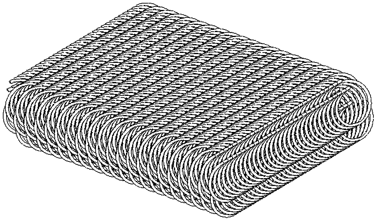
[0023] figure 1 It is a schematic diagram of the metal-rubber structure formed by winding metal wires. Metal rubber is to use a certain method to stack the stretched helical metal wires according to the quality, and then use the cold stamping process to make a shape that meets the requirements. Its cross-sectional shape is as follows: figure 2 shown. The stiffness and damping characteristics of metal rubber can be changed by changing parameters such as material, compression ratio, porosity and thickness.

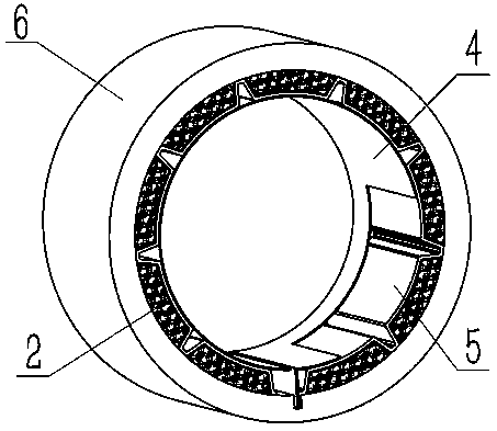
[0024] The cross-sectional shape of the separate elastic foil is as image 3 As shown, the foil thickness δ depends on its design stiffness, generally between 0.1mm and 0.4mm. The shape of the top is arc-shaped with radius r, and there are strip-shaped protrusions pointing to the inner surface of the bearing sleeve on both side...


PUM


Abstract

The invention relates to a radial elastic aero dynamic bearing, in particular to an aero dynamic bearing with a metal rubber and elastic chaff composite support structure. The novel aero bearing with the composite support structure comprises a bearing sleeve, metal rubber blocks, elastic chaffs and a top chaff. The elastic support structure is formed by superimposing the metal rubber blocks and the elastic chaffs. One end of each elastic chaff and one end of the top chaff are fixed on the bearing sleeves, and the other end of each elastic chaff and the other end of the top chaff are free. The metal rubber blocks are formed by metal wire winding and a cold stamping technology, and surrounded and fixed by the elastic chaffs and the bearing sleeve. The elastic chaffs are higher in rigidity and lower in damping, while a metal rubber material is lower in rigidity and high in damping. According to the aero bearing, the elastic support structure of the aero bearing is improved and formed by superimposing the metal rubber blocks and the elastic chaffs, so that the bearing has the characteristic of high rigidity and damping, the carrying capacity of the bearing is improved, the vibration impact is reduced, and the reliability of the bearing is improved.

Description


Claims


Application Information

Patent Timeline
Owner HUNAN UNIV
Why Eureka
Try Eureka