
LED spotlight

A technology of LED spotlights and LED light sources, applied in the field of lighting, can solve the problems of high cost, complex structure, low efficiency, etc., and achieve the effect of low cost, good effect and long service life

Active Publication Date: 2013-12-11
佛山市千百镀灯饰照明有限公司
View PDF7 Cites 7 Cited by
  • Summary
  • Abstract
  • Description
  • Claims
  • Application Information

AI Technical Summary

Problems solved by technology

[0002] Existing LED spotlights achieve directional beams by installing lenses or reflector cups, which are high in cost, low in efficiency, and complex in structure

Method used


Image

  • LED spotlight
  • LED spotlight
  • LED spotlight

Examples


Embodiment 2

[0030] Such as Image 6 , Figure 7 Shown is a schematic structural diagram of another LED spotlight of the present invention. In this embodiment, the structure of the connector is different from that of Embodiment 1. An LED spotlight in this embodiment includes a lamp cap 21, a glass lamp cup body 22, and a lamp cover 23. A power supply 24 and an LED light source 25 are arranged in the glass lamp cup body. slot 221, the edge of the installation port is provided with a lower ventilation slot 222, the bottom of the lamp cap 21 is provided with a connector, the connector includes a base 26 arranged inside the lamp cap and a connecting rod 27 and two connecting rods arranged at the bottom of the base 26 A buckle 28, the side wall of the base 26 is provided with an external thread 261, the connecting rod 27 is arranged at the center of the inner surface of the lamp cap, and is integrally formed with the lamp cap, and the buckle 28 is arranged on both sides of the connecting rod. ...

Embodiment 3

[0032] Such as Figure 8 As shown, it is a schematic structural diagram of an LED spotlight according to Embodiment 3 of the present invention, which includes a lamp cap 31, a glass lamp cup body 32 and a lamp cover 33, and an upper ventilation slot 321 is provided on the edge of the lamp opening of the glass lamp cup body. The edge of the installation opening is provided with a lower ventilation slot 322 . However, in the present invention, except that the structure of the lamp cap 31 and the glass lamp cup body 32 are different from those of the lamp cap 21 and the glass lamp cup body 22 in the second embodiment, the others are the same as those in the second embodiment, and will not be repeated here.

Embodiment 4

[0034] In the present invention, the lamp holder is not limited to the above-mentioned structural form, and can also be as Figure 9 shown.

[0035] In the present invention, it is also possible to set the upper ventilation slot at the lamp opening of the glass lamp cup body alone, or to set the lower ventilation slot at the installation port of the glass lamp cup body alone, and the number of the upper ventilation slots and the lower ventilation slots can be adjusted according to the needs. to set.

[0036] In the present invention, besides glass, the lamp cup body can also be made of plastic, metal or ceramics.


PUM


Abstract

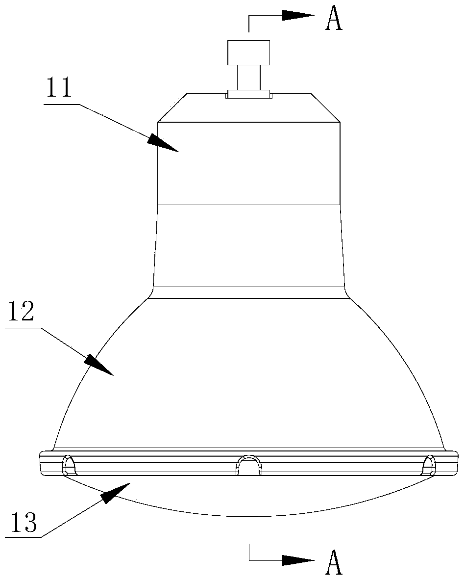
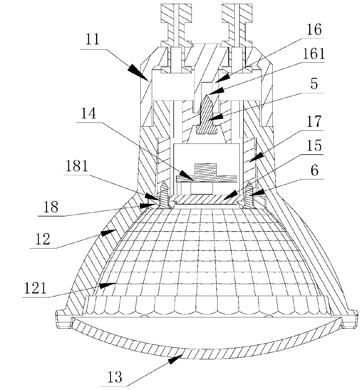
The invention provides an LED spotlight. The LED spotlight comprises a lamp holder, a lamp cup body and a lamp cover, wherein a heat dissipation part, a power source and an LED light source are arranged in the lamp cup body, a plastic baffle is arranged below the LED light source, the lamp cup body is a glass lamp cup body, lattice patterns are arranged on the inner surface of the glass lamp cup body, a reflective dielectric film is arranged on the lattice patterns in a plating mode, and the lattice patterns carry out light distribution according to the light-emission characteristic of the LED light source, and carry out light reflection on light of the LED light source to form a fixed light beam angle. According to the LED spotlight, due to the fact that the glass lamp cup body serves as an outer shell, the situation that a lens or a reflection cup is installed additionally to achieve the directional light beam angle is not needed, and the LED spotlight is simple in structure, low in cost, long in service life and good in lighting effect.

Description

technical field [0001] The invention relates to the technical field of lighting, in particular to an LED spotlight. Background technique [0002] Existing LED spotlights realize directional light beams by installing lenses or reflector cups, which have high cost, low efficiency and complex structure. Contents of the invention [0003] The invention aims to overcome the shortcomings of the prior art, and provides an LED spotlight with simple structure, good heat dissipation effect and long service life, which has a good market application prospect. [0004] An LED spotlight, which includes a lamp cap, a lamp cup body, and a lamp cover. The lamp cup body is provided with a power supply and an LED light source, a heat sink is provided above the power supply, and a plastic baffle is provided below the LED light source. The inner surface of the lamp cup body is provided with a grid pattern, and the grid pattern is coated with a reflective medium film. The grid pattern distribu...

Claims


Application Information

Patent Timeline
Patent Type & Authority Applications(China)
IPC IPC(8): F21S2/00F21V7/22F21V29/00F21Y101/02F21V29/503F21V29/83F21V29/89
Inventor 邹正康
Owner 佛山市千百镀灯饰照明有限公司
Learn More