
Three-line-array camera image collaborative absolute radiometric calibration and compensation method

An absolute radiometric calibration and correction method technology, which is applied in the radiometric calibration and radiometric correction processing of three-line array camera images of surveying and mapping optical remote sensing satellites, and in the field of absolute radiometric calibration and correction of three-line array camera images, which can solve calibration and correction The results lacked correlation, the spectral response curve parameters of the three-line array camera were not normalized, and the calibration results and correction effects of the three-line array camera were not considered.

Active Publication Date: 2013-12-11
SPACE STAR TECH CO LTD
View PDF3 Cites 21 Cited by
  • Summary
  • Abstract
  • Description
  • Claims
  • Application Information

AI Technical Summary

Problems solved by technology

The main problems and defects of this processing method in the absolute radiometric calibration and correction processing of the remote sensing images of the three-line array cameras are: the sub-satellite point imaging is taken as the basic assumption, and the difference in the observation direction of the three-line array cameras is not considered to affect the calibration results. and correction effect; the spectral response curve parameters of the three-line array camera have not been normalized, and the relationship between the spectral responses between different cameras has not been constructed, resulting in a lack of synergistic correlation between calibration and correction results

Method used


Image

  • Three-line-array camera image collaborative absolute radiometric calibration and compensation method
  • Three-line-array camera image collaborative absolute radiometric calibration and compensation method
  • Three-line-array camera image collaborative absolute radiometric calibration and compensation method

Examples


Embodiment Construction

[0073] The inventive method is further described below:

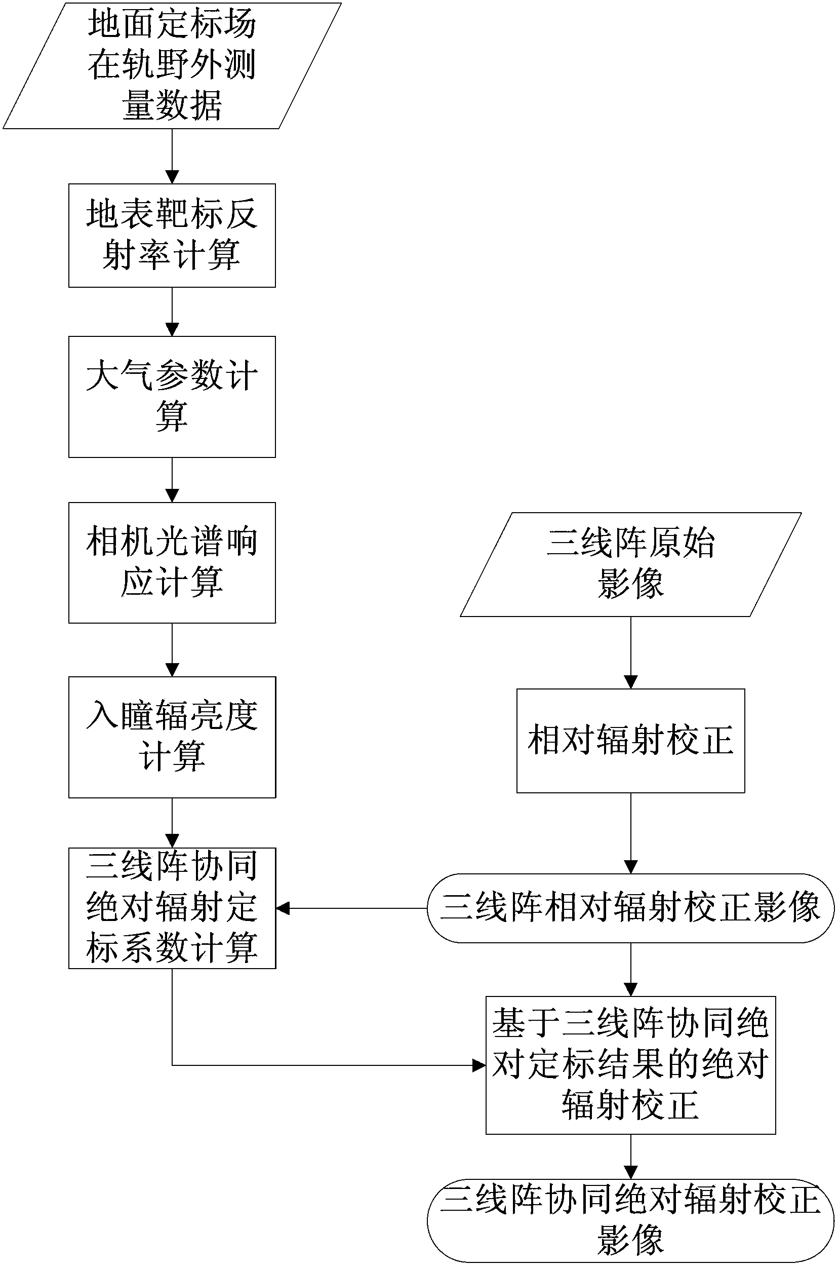
[0074] 1) According to the independent laboratory relative calibration coefficients of the front-sight, front-sight and rear-sight cameras of the three-line array of remote sensing satellites obtained from the measurement, the original image of the three-line array camera of the radiometric calibration field target is calculated camera by image by using the gray scale linear transformation method The relative radiation correction is carried out to obtain the relative radiation correction image of the target in the radiation calibration field.

[0075] 1.1) Obtain the independent laboratory relative calibration coefficients of the front-sight, front-sight and rear-sight cameras of the three-line array of remote sensing satellites: obtain the relative calibration coefficients of each detector of each camera of the three-line array camera gain relative(k,i) with offset relative(k,i) , where gain relative(k,i) Indicates g...


PUM


Abstract

The invention discloses a three-line-array camera image collaborative absolute radiometric calibration and compensation method. The three-line-array camera image collaborative absolute radiometric calibration and compensation method comprises following steps: 1) respective relative radiometric calibration of three-line-ray camera images; 2) calculation of ground target reflectivity; 3) calculation of atmosphere parameters; 4) respective spectral response calculation of the three-line-ray camera; 5) respective entrance pupil radiance calculation of the three-line-array camera; 6) calculation of three-line-array collaborative absolute radiometric calibration coefficients; and 7) absolute radiometric correction based on the three-line-array collaborative absolute radiometric calibration coefficients. According to the three-line-array camera image collaborative absolute radiometric calibration and compensation method, an unified model is constructed based on the radiation response relationship of front sight, fore sight and back sight images of the three-line-array camera, so that actual spectral characteristics of the ground target are reflected by the radiation response of three-line-array imagines, and the foundation for photogrammetric stereoplotting and remote sensing quantitative application is provided.

Description

technical field [0001] The invention relates to a three-line array camera image collaborative absolute radiation calibration and correction method, which belongs to the technical field of remote sensing satellite image processing and is used for surveying and mapping optical remote sensing satellite three-line array camera image radiation calibration and radiation correction processing. Background technique [0002] The three-line array camera is one of the main optical loads carried by surveying and mapping optical remote sensing satellites. It has cameras in three observation directions: front view (also known as down view), front view and rear view. Precisely calibrated and controlled geometric relationships. Through the three-line array camera, the imaging of the same area and the same target at the sub-satellite point, the front of the flight track and the rear of the flight track can be realized on a single satellite, and through the processing and analysis of images i...

Claims


Application Information

Patent Timeline
Patent Type & Authority Applications(China)
IPC IPC(8): G01C25/00
Inventor 张晓郝胜勇胡沅张荞
Owner SPACE STAR TECH CO LTD
Learn More