Switch cabinet equipped with isolating switches, vacuum circuit breakers and grounding switches

A vacuum circuit breaker and isolating switch technology, which is applied in the field of switchgear, can solve the problems of low operation reliability, safety hazards, cumbersome operation, etc., and achieve the effect of perfect interlocking function, high safety, and simple operation

Active Publication Date: 2013-12-11
厦门闽光电气实业有限公司
View PDF5 Cites 17 Cited by
  • Summary
  • Abstract
  • Description
  • Claims
  • Application Information

AI Technical Summary

Problems solved by technology

[0002] The switchgear is a commonly used power distribution equipment in the power system. The switchgear usually includes cabinets, circuit breakers, disconnectors, grounding switches and other mechanisms. Safety is one of the most important technical indicators of the switchgear. In order to achieve the "five "Prevention" requirements, that is, to prevent closing with load, preventing mistakenly entering live intervals, preventing closing with grounding wires, preventing pulling knife gates with load, and preventing live connection with grounding wires. Various manufacturers have designed various switches in the switchgear. However, the main problem at present is that the interlocking function of some switchgears is not perfect, the reliability of the action is low, and there are some safety hazards, and the interlocking mechanism of the other part of the switchgear is complicated, the operation is cumbersome, and the versatility is poor.

Method used


Image

  • Switch cabinet equipped with isolating switches, vacuum circuit breakers and grounding switches
  • Switch cabinet equipped with isolating switches, vacuum circuit breakers and grounding switches
  • Switch cabinet equipped with isolating switches, vacuum circuit breakers and grounding switches

Examples


Embodiment Construction

[0039] The present invention will be further described in detail below in conjunction with the drawings and specific embodiments.

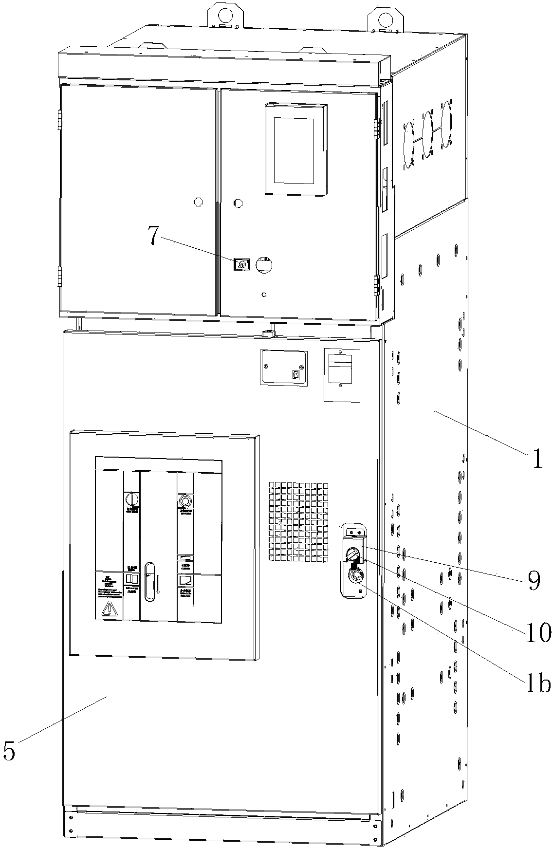
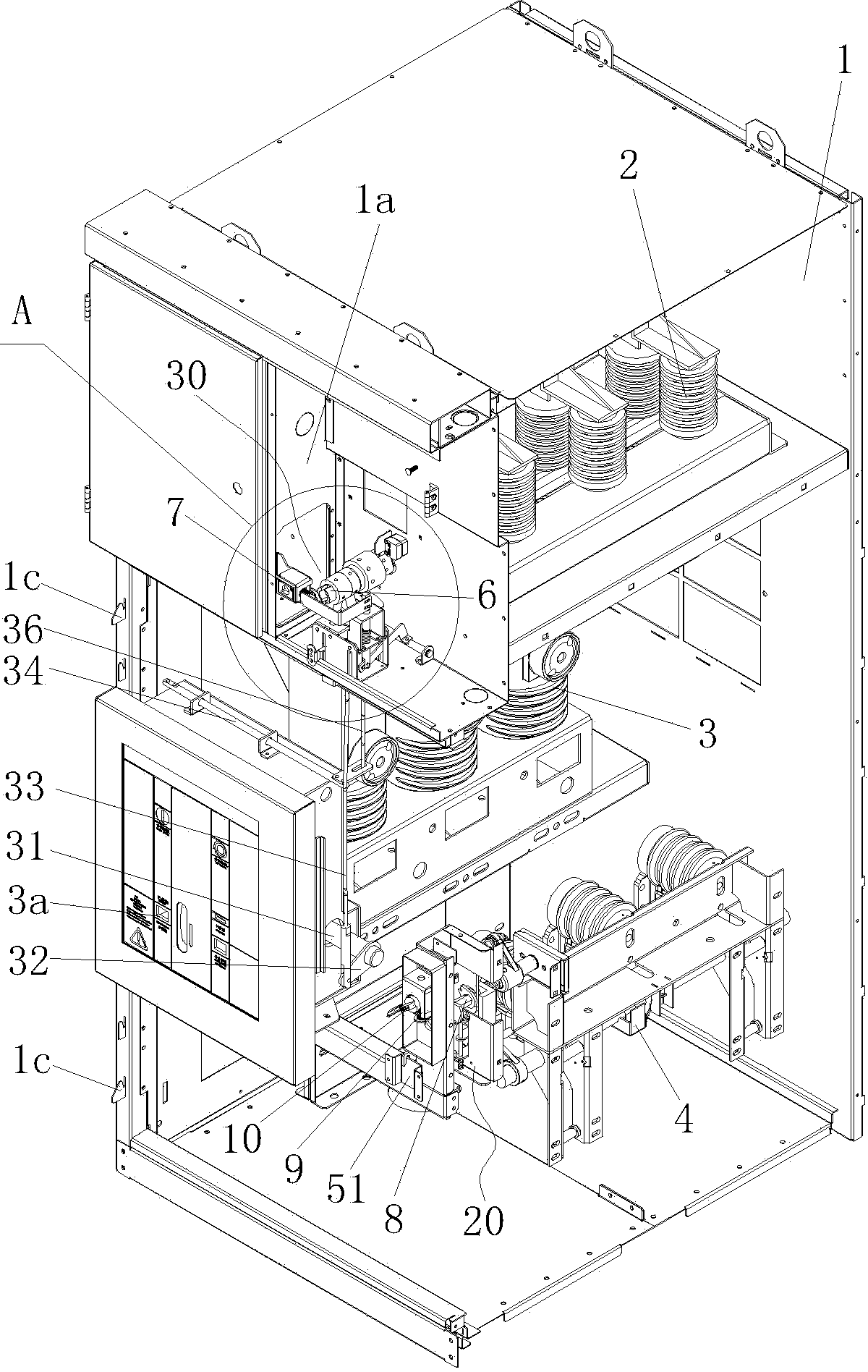
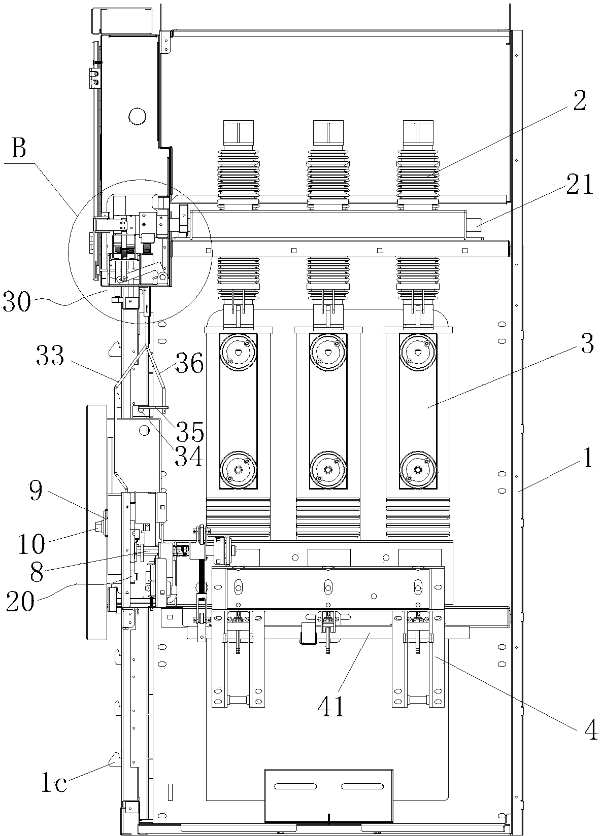
[0040] Figure 1 to Figure 9 As shown, a switch cabinet equipped with an isolating switch, a vacuum circuit breaker and a grounding switch includes a cabinet body 1. The upper part of the cabinet body 1 is equipped with an isolating switch 2, and the middle part of the cabinet body 1 is equipped with a vacuum circuit breaker 3, and the cabinet body The lower part of 1 is equipped with a grounding switch 4, the upper part of the front side of the cabinet 1 is provided with an isolation switch operation room 1a, and the lower part of the front side of the cabinet 1 is provided with a cabinet door 5;

[0041] An operating sleeve 6 is connected to the operating shaft 21 of the isolating switch 2 and is located in the isolating switch operating room 1a, and the first program lock 7 is installed in the isolating switch operating room 1a;

[0042] An operating...


PUM


Abstract

The invention discloses a switch cabinet equipped with isolating switches, vacuum circuit breakers and grounding switches. The cabinet switch includes a cabinet body and a cabinet door. An operating sleeve corresponding to a first program lock is connected with an isolating-switch operating shaft. An operating shaft driving the grounding switches to switch on and switch off is installed on the cabinet body and the cabinet body is provided with an operation hole corresponding to the operating shaft and the operating shaft is corresponding to a second program lock. The first program lock and the second program lock share one key which is used for opening the locks and is not separated from either of the locks. The front side of the cabinet body is provided with a first mutual-locking mechanism for the cabinet door and the grounding switches. The first mutual-locking mechanism includes a lock catch fixed on the cabinet door, a first fan-shaped plate and a first limit board which are installed on the operating shaft, a first support installed on the cabinet body, a latch hook installed on the first support and an L-shaped gag lever post which is in cooperation with the latch hook and fixed with the first limit plate. The operating shaft restraints the second program lock from being opened through a second cam and a second limit plate when the grounding switches are switched on. The switch cabinet is perfect in mutual-locking function, simple to operate and high in security.

Description

Technical field [0001] The invention relates to a switch cabinet, in particular to a switch cabinet equipped with an isolating switch, a vacuum circuit breaker and a grounding switch. Background technique [0002] Switch cabinets are commonly used power distribution equipment in power systems. Switch cabinets usually include cabinets, circuit breakers, isolating switches, grounding switches and other mechanisms. Safety is one of the most important technical indicators of switch cabinets. In order to achieve "five The requirements of “prevention” are to prevent closing on load, prevent inadvertent entry of the live interval, prevent closing with grounding wire, prevent the knife switch with load, and prevent the ground wire from hanging on the ground. Various manufacturers have designed various types of switches in the switch cabinet. This kind of interlocking mechanism, but the main problem at present is that the interlocking function of some switch cabinets is not perfect, the o...

Claims


Application Information

Patent Timeline
Patent Type & Authority Applications(China)
IPC IPC(8): H02B11/133
Inventor 苏水郑房帅王清鑫
Owner 厦门闽光电气实业有限公司
Why Eureka
Try Eureka