Auxiliary power supply device of guide rail electric locomotive, guide rail electric locomotive and power supply method of guide rail electric locomotive

A technology for electric locomotives and auxiliary power supply, applied in circuit devices, output power conversion devices, electrical components, etc., can solve the problems of large volume of auxiliary power supply equipment, inconvenient maintenance and disassembly, high manufacturing cost, etc., and achieve small space occupation and convenience Dismantling and repairing, strong maintainability

Pending Publication Date: 2020-11-20
XIAN ACTIONPOWER ELECTRIC
View PDF12 Cites 0 Cited by
  • Summary
  • Abstract
  • Description
  • Claims
  • Application Information

AI Technical Summary

Problems solved by technology

[0004] The purpose of the present invention is to solve the shortcomings of the existing auxiliary power supply equipment, such as large volume, inconvenient maintenance and disassembly, few functions, and high manufacturing cost, and provide a new type of auxiliary power supply device for guide rail electric locomotives, guide rail electric locomotives, etc. Locomotive and its power supply method

Method used


Image

  • Auxiliary power supply device of guide rail electric locomotive, guide rail electric locomotive and power supply method of guide rail electric locomotive
  • Auxiliary power supply device of guide rail electric locomotive, guide rail electric locomotive and power supply method of guide rail electric locomotive
  • Auxiliary power supply device of guide rail electric locomotive, guide rail electric locomotive and power supply method of guide rail electric locomotive

Examples


Embodiment Construction

[0048] Below in conjunction with accompanying drawing and specific embodiment content of the present invention is described in further detail:

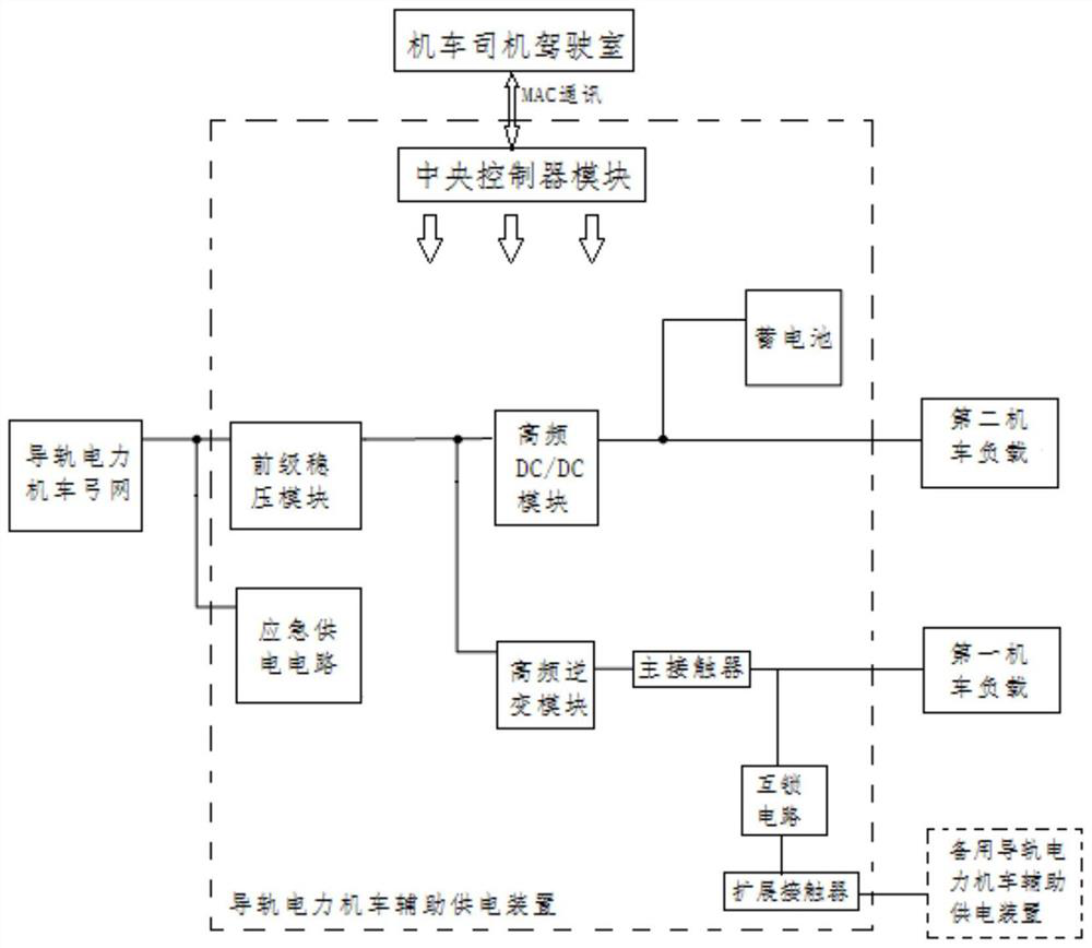
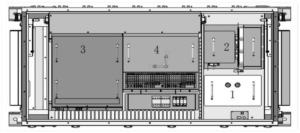
[0049] Such as Figure 1-Figure 3 As shown, an auxiliary power supply device for a guide rail electric locomotive includes a central controller module 1 inserted in the same housing, two pre-stage voltage stabilizing modules, a high-frequency inverter module 3, a high-frequency DC / DC module 4, a battery, Emergency power supply circuit, interlock circuit, main contactor and extension contactor.

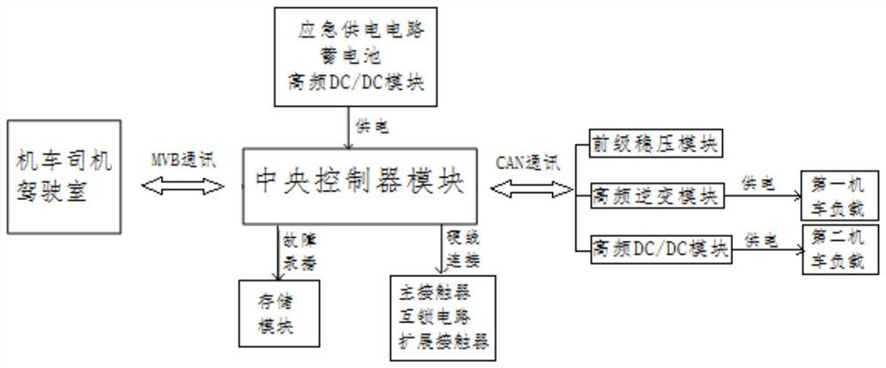
[0050] The MVB communication mechanism is adopted between the central controller module and the locomotive driver's cab, and the CAN communication mechanism is adopted between the pre-stage voltage stabilization module, high-frequency inverter module and high-frequency DC / DC module, and the interlock circuit and main contact The controller and the expansion contactor are connected by hard wires; it should be noted that the electrical wiring met...


PUM


Abstract

The invention provides an auxiliary power supply device of a guide rail electric locomotive, the guide rail electric locomotive and a power supply method of the guide rail electric locomotive, and solves the problems that existing auxiliary power supply equipment is large in size, inconvenient to maintain and detach, few in functions and high in manufacturing cost. The auxiliary power supply device comprises a central controller module, a preceding-stage voltage stabilization module, a high-frequency inversion module, a high-frequency DC/DC module, a main contactor and a storage battery. The central controller module is in communication connection with a locomotive driver cab, the preceding-stage voltage stabilization module, the high-frequency inversion module and the high-frequency DC/DCmodule and is electrically connected with the main contactor. The input end of the preceding-stage voltage stabilization module is electrically connected with a pantograph-catenary of the guide railelectric locomotive, and the output end of the preceding-stage voltage stabilization module is electrically connected with the input ends of the high-frequency inversion module and the high-frequencyDC/DC module; the output end of the high-frequency inversion module is electrically connected with a first locomotive load needing alternating current through a main contactor; the output end of the high-frequency DC/DC module is electrically connected with a second locomotive load needing direct current and the storage battery; and the storage battery is used for supplying power to the central controller module.

Description

technical field [0001] The invention belongs to the power supply technology of a guide rail electric locomotive, and in particular relates to an auxiliary power supply device for a guide rail electric locomotive, a guide rail electric locomotive and a power supply method thereof. Background technique [0002] With the continuous improvement of living standards and the continuous development of the transportation system, electric locomotives have gradually become one of the main means of transportation in large and medium-sized cities. As the core component of subway vehicles, the auxiliary power system of subway vehicles is an indispensable and important system components. In recent years, due to environmental pollution, the country has vigorously promoted electric clean energy, so guide rail cars have developed rapidly in recent years. Due to the various installation forms and high volume requirements of electric guide rail trams, higher requirements are placed on power su...

Claims


Application Information

Patent Timeline
Patent Type & Authority Applications(China)
IPC IPC(8): H02M3/335H02M3/158H02M7/537H02J9/06
CPCH02M3/33569H02M3/158H02M7/537H02J9/061
Inventor 席建强李海波白小青
Owner XIAN ACTIONPOWER ELECTRIC
Why Eureka
Try Eureka