
Cutting fluid filtering device having filter washing function

一种过滤装置、切削液的技术,应用在固定式滤芯过滤器、过滤分离、制造工具等方向,能够解决不能自动变更逆洗的时间、未考虑调整间隔(时间等问题

Active Publication Date: 2013-12-18
FANUC LTD
View PDF4 Cites 5 Cited by
  • Summary
  • Abstract
  • Description
  • Claims
  • Application Information

AI Technical Summary

Problems solved by technology

[0012] In the above-mentioned prior art, in order to change the interval (time) from the completion of backwashing of the filter to the next backwashing, it is necessary to change the pressure at which the differential pressure switch 14 operates, or to change the setting of the differential pressure for backwashing. value, or change the value of the timer that determines the backwash interval time, the backwash time cannot be automatically changed according to the degree of filter clogging
Furthermore, although it is described that the compressed air supply time during backwashing is changed according to the degree of filter clogging, adjustment of the interval (time) from the completion of backwashing of the filter to the next backwashing is not considered.

Method used


Image

  • Cutting fluid filtering device having filter washing function
  • Cutting fluid filtering device having filter washing function
  • Cutting fluid filtering device having filter washing function

Examples


Embodiment Construction

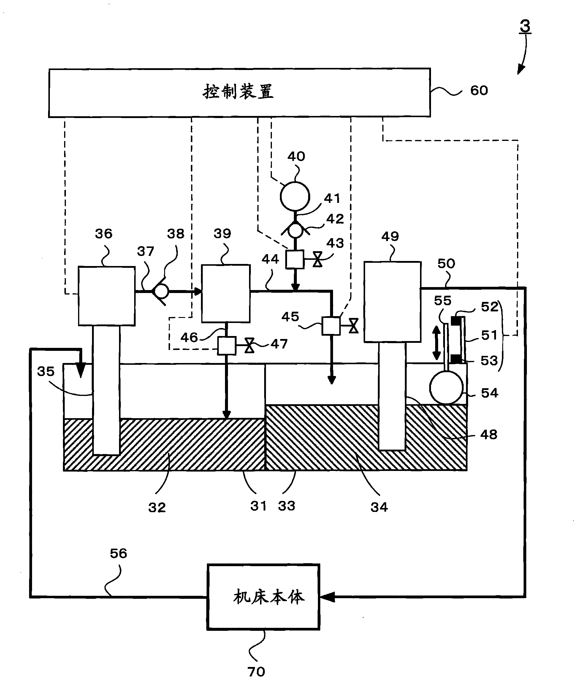
[0034] use figure 1 One embodiment of the cutting fluid filter device of the present invention will be described.

[0035] Symbol 3 is a cutting fluid filter device, symbol 31 is a dirty tank, symbol 32 is a cutting fluid containing chips, symbol 33 is a clean tank, symbol 34 is a purified cutting fluid, symbol 35 is a pipeline, and symbol 36 is a filter pump , symbol 37 is a pipeline, symbol 38 is a one-way valve, symbol 39 is a filter container with a filter (not shown) installed inside to remove impurities from the cutting fluid containing impurities, symbol 40 is an air source, and symbol 41 is a pipeline, symbol 42 is a one-way valve, symbol 43 is an air supply valve, symbol 44 is a pipeline, symbol 45 is an outflow side valve, symbol 46 is a pipeline, symbol 47 is a discharge valve, symbol 48 is a pipeline, symbol 49 is a pump, 50 is a pipe, 51 is a sensor supporting member, 52 is a proximity sensor for upper limit detection, 53 is a proximity sensor for lower limit de...


PUM


Abstract

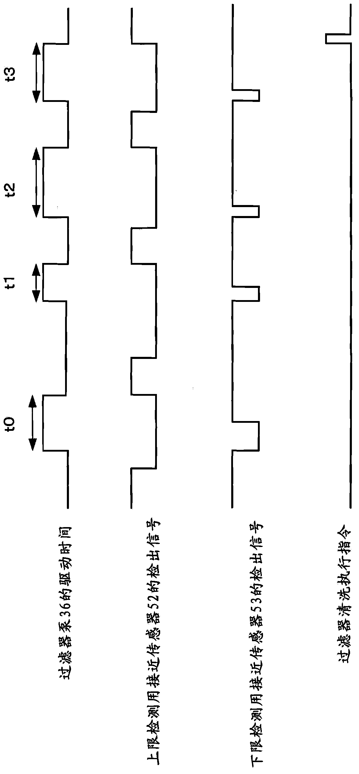
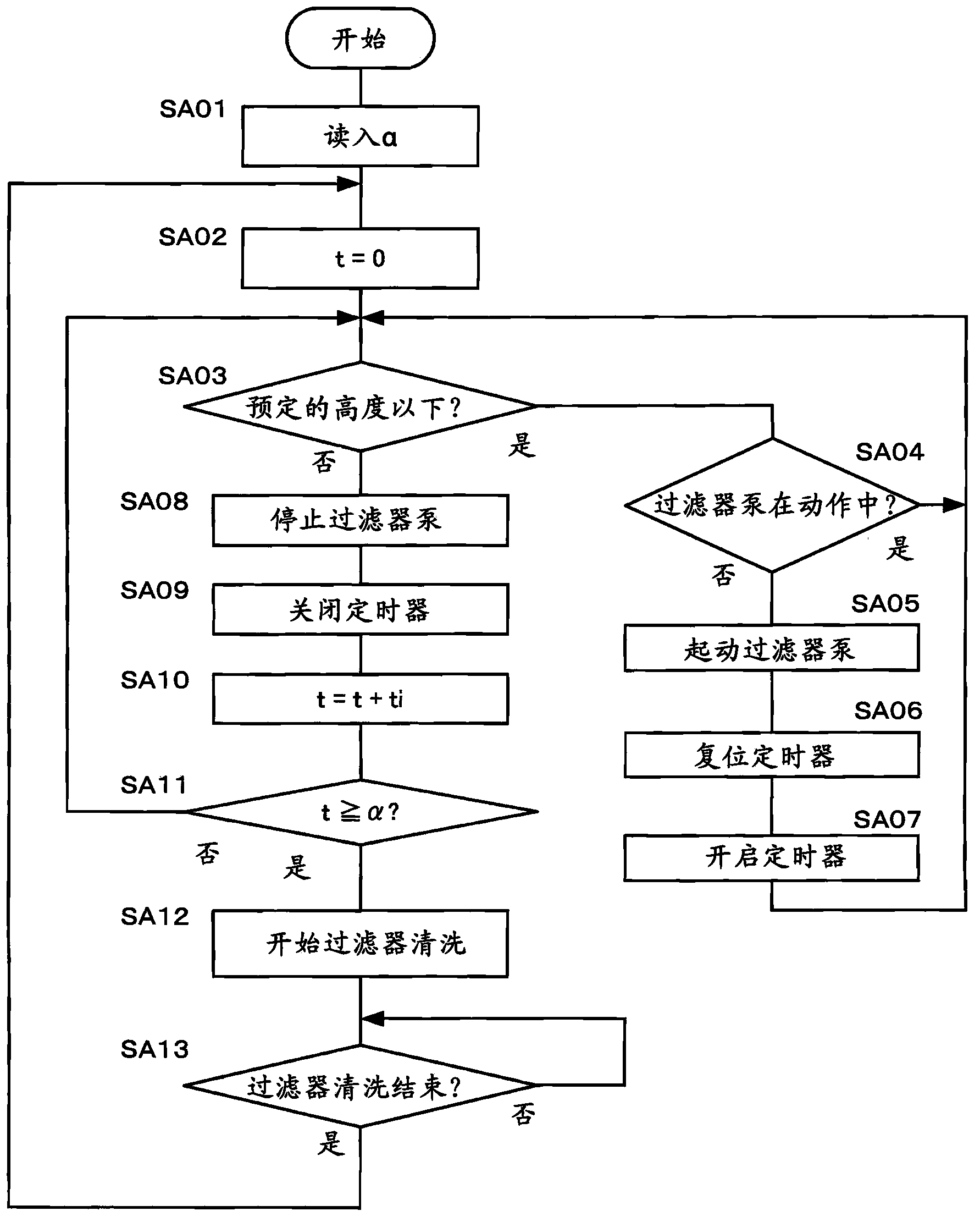
A cutting fluid filtering device having a filter washing function drives a pump to supply a cutting fluid to a filter when the fluid level of a tank that stores the cutting fluid filtered by the filter becomes equal to or lower than a predetermined height. In addition, the cutting fluid filtering device issues an instruction to execute washing of the filter when the operation times of the pump are totalized and the total value becomes equal to or longer than a preset washing operation interval time of the filter.

Description

technical field [0001] The present invention relates to a cutting fluid filtering device used in machine tools to remove chips or sludge mixed in cutting fluid. Background technique [0002] In machine tools, impurities such as chips and sludge generated during machining are mixed into the cutting fluid, which adversely affects the performance and reliability of the machine, so filters are used to remove these impurities. For this filter, cleaning of the filter is performed for the purpose of maintaining purification performance and prolonging life. As the cleaning method, for example, as described in JP-A-2006-272474, JP-A-2006-255833, and JP-A-2001-252847, the direction in which the cutting fluid flows during normal use may be The cutting fluid flows in the opposite direction, and backwashing is performed to remove chips or sludge adhering to the filter from the filter. [0003] Here, the outline of the above-mentioned backwashing operation will be described. First, clo...

Claims


Application Information

Patent Timeline
Patent Type & Authority Applications(China)
IPC IPC(8): B01D35/02B01D35/14B01D35/143B01D35/16B23Q11/10
CPCB01D29/62B01D29/605B01D29/66B01D35/027B01D37/045B23Q11/1069
Inventor 石原光告
Owner FANUC LTD
Learn More