Rear-door built-in rear-view mirror and its position adjustment method
An adjustment method and rearview mirror technology, applied in the field of automobile rearview mirrors, can solve problems such as poor safety, achieve the effects of preventing safety accidents, simple and compact structure, and exercising hand strength
- Summary
- Abstract
- Description
- Claims
- Application Information
AI Technical Summary
Problems solved by technology
Method used
Image
Examples
Embodiment 1
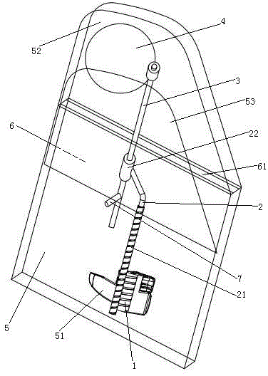
[0023] Embodiment one, see figure 1 , a built-in rearview mirror for a rear car door, comprising a threaded column 1, a connecting rod 2, a support rod 3 and a rearview mirror 4.
[0024] The threaded column 1 is arranged on the opening handle 51 in the rear door. The threaded post 1 is located inside the rear door 5 . The structure of opening handle 51 in the rear car door, the installation method, the action mode are all existing on the car at present. Opening handle 51 is installed on the inner side of rear door 5 in the car door. The threaded post 1 is parallel to the axis when the opening handle 51 in the rear car door rotates. A rearview mirror accommodating cavity 6 is arranged in the rear door 1 . The rearview mirror accommodating cavity 6 is a flat structure. The arrangement as a flat structure can make the size increase of the rear door along the vehicle body width direction caused by the arrangement of the rearview mirror accommodating cavity smaller. The rear...
Embodiment 2
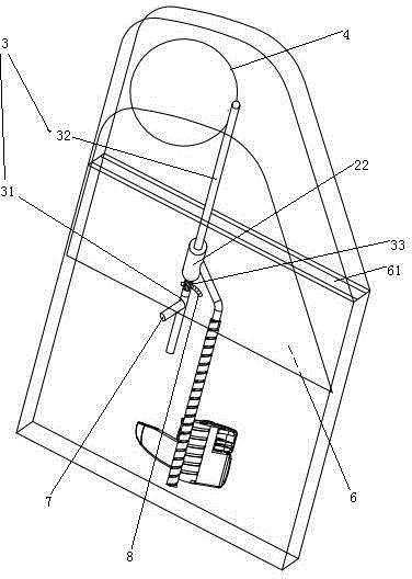
[0031] Embodiment two, see figure 2 , the difference from the first embodiment is: the rearview mirror housing cavity 6 is provided with a circular arc-shaped rack 8 . The rack 8 is coaxial with the hinge shaft 7 . The support rod 3 includes a first section 31 and a second section 32 . The first segment 31 and the second segment 32 are rotatably connected together. The first section 31 is hinged in the rearview mirror accommodating cavity 6 through the hinge shaft 7 . The sliding sleeve 22 is slidingly sleeved on the second segment 32 . The rearview mirror 4 is fixedly connected to one end of the second segment 31 . The other end of the second section 32 is provided with several adjusting teeth 33 for viewing angle direction of the rearview mirror. The viewing angle direction adjustment tooth 33 of the rearview mirror is located on the peripheral surface of the second segment 32 . The viewing angle direction adjustment teeth 33 of the rearview mirror are distributed alo...
Embodiment 3
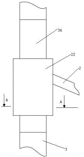
[0033] Embodiment three, see image 3 , The difference with the first embodiment is: the support rod 3 is provided with an inflatable section 34 . The sliding sleeve 22 on the connecting rod 2 is slidably sleeved on the inflatable section 34 .
[0034] see Figure 4 , the inflation section is provided with an inflation bladder 341. Inflatable bladder 341 is made of rubber. The inflatable section also includes several rigid strips 342 . Rigid bar 342 is a stainless steel bar. The rigid strips 342 are distributed along the circumferential direction of the air bladder 341 , that is, the circumferential gaps of the support rods. The rigid strip 342 extends in the axial direction of the inflatable section. The rigid strip 342 is built in and fixed in the wall of the air bladder 341 .
PUM
 Abstract
Description
Claims
Application Information
 - R&D
- Intellectual Property
- Life Sciences
- Materials
- Tech Scout
- Unparalleled Data Quality
- Higher Quality Content
- 60% Fewer Hallucinations
Browse by: Latest US Patents, China's latest patents, Technical Efficacy Thesaurus, Application Domain, Technology Topic, Popular Technical Reports.
© 2025 PatSnap. All rights reserved.Legal|Privacy policy|Modern Slavery Act Transparency Statement|Sitemap|About US| Contact US: help@patsnap.com


