
Stepless regulation constant tension device for hydraulic winch

A stepless adjustment, hydraulic winch technology, applied in the hydraulic field, can solve the problems of complicated and inconvenient operation process, inability to realize constant tension control of wire rope, inability to realize speed control of rope unwinding, etc., to achieve simple and convenient operation, prevent safety accidents, maintain The effect of system oil pressure

Active Publication Date: 2011-08-17
WUHAN MARINE MACHINERY PLANT
View PDF6 Cites 31 Cited by
  • Summary
  • Abstract
  • Description
  • Claims
  • Application Information

AI Technical Summary

Problems solved by technology

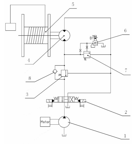
[0004] The purpose of the present invention is to overcome the inability to realize the constant tension control of the steel wire rope under the braking condition of the existing hydraulic winch stepless adjustment constant tension device, the inability to realize the speed control of the rope unwinding under the unwinding condition, and the adjustment of the output capacity of the hydraulic winch Special tools are required to be carried out in the machine room, and the operation process is complicated and inconvenient. A hydraulic winch stepless adjustment constant tension device is provided to realize the function of the hydraulic winch to maintain a constant tension of the wire rope under various working conditions, and can effectively control The speed of unwinding the rope, and the ability to remotely and online adjust the output capacity of the hydraulic winch, has a simple structure, low cost, convenient use, and high safety

Method used


Image

  • Stepless regulation constant tension device for hydraulic winch
  • Stepless regulation constant tension device for hydraulic winch

Examples


Embodiment Construction

[0015] The present invention will be further described in detail below in conjunction with the accompanying drawings and specific embodiments.

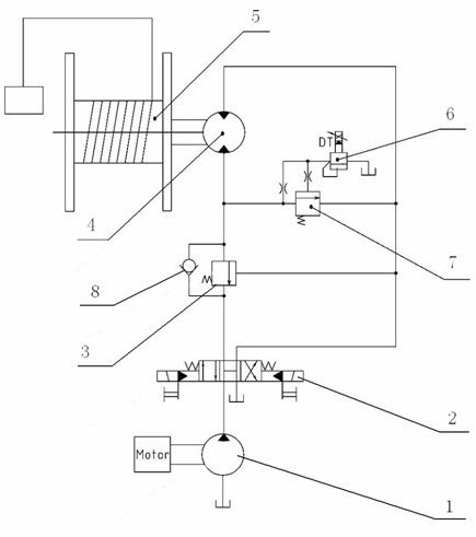
[0016] see figure 1 , the hydraulic principle diagram of the hydraulic winch stepless adjustment constant tension device of the present invention, the hydraulic winch stepless adjustment constant tension device consists of a power pump group 1, a reversing valve 2, a hydraulic motor 4, a winch 5, a balance valve 3, a one-way valve 8, The motor safety valve consists of 7 components. The oil inlet of the power pump unit 1 is connected to the oil tank, the oil outlet of the power pump unit 1 is connected to the oil port on the rope-receiving side of the hydraulic motor 4, the oil port on the rope-releasing side of the hydraulic motor 4 is connected to the oil tank, and the shaft of the winch 5 is connected to the oil port of the hydraulic motor 4. The output shaft of the hydraulic winch is connected to the output shaft. The hydraulic wi...


PUM


Abstract

The invention discloses a stepless regulation constant tension device for a hydraulic winch, consisting of a power pump set, a reversing valve, a hydraulic motor, a winch, a one-way valve, a balance valve and a motor safety valve, wherein the power pump set is connected with an oil inlet of the reversing valve; a first oil exchange port of the reversing valve is connected with an oil return port of the balance valve; an oil inlet of the balance valve is connected with a rope folding side oil port of the hydraulic motor; a rope release side oil port of the hydraulic motor is connected with a second oil reversing port of the reversing valve; an oil outlet of the reversing valve is connected with an oil tank; a control port of the balance valve is connected with an oil path between the rope release side oil port of the hydraulic motor and the reversing valve; the one-way valve is connected between the oil inlet and the oil return port of the balance valve in parallel; the motor safety valve is connected between the rope folding side oil port and the rope release side oil port of the hydraulic motor in parallel; and the winch is connected with the hydraulic motor. The device achieves the function of keeping the tension of a steel wire rope constant when the hydraulic winch is positioned under various work conditions and can be used for carrying out remote on-line adjustment on theoutput capacity of the hydraulic winch. The stepless regulation constant tension device has the advantages of simple structure, low cost, convenience for use and high safety.

Description

technical field [0001] The invention relates to a hydraulic winch, in particular to a stepless adjustment constant tension device of a hydraulic winch, which belongs to the field of hydraulic technology. Background technique [0002] At present, most of the machines used to lift and tow heavy objects such as cranes, towing machines, and mooring winches use hydraulic winches. With the continuous improvement of the rated lifting capacity of lifting machinery and the increasing complexity of the working environment of Higher requirements are put forward for the safety of hydraulic winches, not only requiring hydraulic winches to ensure slow, stable and controllable speed during hoisting, operation, acceleration, braking, etc., but also requiring hydraulic winches to adapt to load changes and maintain wire rope tension. Constant capacity to prevent safety accidents where the wire rope exceeds the maximum bearing capacity due to a sudden increase in load and breaks. Especially f...

Claims


Application Information

Patent Timeline
IPC IPC(8): B66D1/50B66D1/54
Inventor 王荣军徐兵熊小平杨振华施维枝
Owner WUHAN MARINE MACHINERY PLANT
Learn More