Method for underbalanced tubing descending, non-well-killing gas lifting, rotary pumping, pump maintaining and tubing maintaining

An underbalanced tubing technology, applied in the fields of snubbing gas lift, underbalanced tubing, pumping, pump inspection and tubing maintenance, which can solve the problems of weakening reservoir protection effect, blocked production channels, and increased operation cycle , to achieve the effect of maintaining production capacity improvement, simplifying production operations, and reducing oil production costs

Active Publication Date: 2013-12-18
CNPC XIBU DRILLING ENG
View PDF10 Cites 10 Cited by
  • Summary
  • Abstract
  • Description
  • Claims
  • Application Information

AI Technical Summary

Problems solved by technology

[0004]The present invention provides a method for under-balanced tubing, snubbing gas lift, pumping, pump inspection and tubing inspection, which overcomes the above-mentioned deficiencies in the prior art , which can effectively solve the problems of blocked production channels, increased operation cycle, weakened reservoir protection effect of independent operations and high oil production cost in the oil recovery process

Method used


Image

  • Method for underbalanced tubing descending, non-well-killing gas lifting, rotary pumping, pump maintaining and tubing maintaining

Examples


Embodiment 1

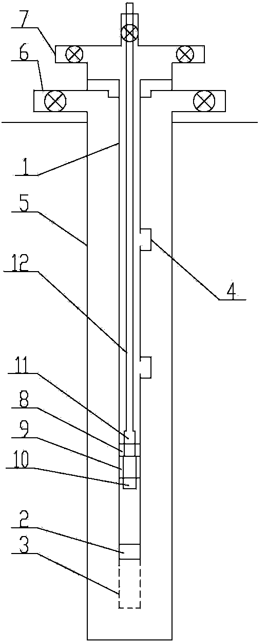
[0018] Embodiment 1: The under-balanced oil tubing, snubbing gas lift, transfer pumping, pump inspection and tubing maintenance methods are carried out as follows: first step, the bottom end of the tubing string 1 is fixed sequentially from top to bottom Install the blowout preventer 2 in the oil pipe and the basket 3, install the float valve in the blowout preventer 2 in the oil pipe, fix the movable device in the blowout preventer 2 in the oil pipe, and install not less than one in the middle of the oil pipe string 1 Forward gas lift valve 4, fixedly install pump seat 8 in tubing string 1, fixedly install pump sealing device 9 on the inner side of the lower part of pump seat 8, and fixedly install pump sealing valve on pump sealing device 9, close the upper end of casing 5 Fixed on the wellhead, the oil production spool 6 is fixedly installed on the casing 5 above the wellhead; in the second step, the tubing string 1 is lowered into the casing 5, and then the upper end seat ...

Embodiment 2

[0019] Embodiment 2: The difference from the above embodiment is that after the eighth step is completed, the following steps are followed in sequence: the ninth step is to lower the tubing string 1 into the casing 5, and then put the upper end of the tubing string 1 The seat is hung in the oil production spool 6, and finally the seat of the Christmas tree 7 is sealed on the oil production spool 6, wherein: during the running process, the pressure between the casing 5 and the tubing string 1 is controlled by rotating the blowout preventer; the tenth The first step is to put a special core pipe into the tubing string 1, lower the special core pipe to the blowout preventer 2 in the tubing, and push the movable device downwards by the special core pipe so that the inside of the blowout preventer and the tubing string 1 communicate with the well. Establish the production channel; in the eleventh step, the oil well pump 11 is fixedly installed on the lower end of the oil well pump...

Embodiment 3

[0020] Embodiment 3: As an optimization of the above-mentioned embodiment, the blowout prevention device 2 in the oil pipe is a pipe-poke type oil pipe float valve, and a float valve valve is installed in the pipe-poke type oil pipe float valve, and the movable device is a float valve valve. In the ninth step During the running of the tubing string 1 into the casing 5, the positive circulation operation is performed on the tubing string 1 running into different well sections. When the positive circulation operation starts each time, the float valve valve and seal on the tubular tubing float valve The sealing pump valves on the pump 9 are automatically opened, and after the positive cycle operation is completed, the sealing pump valves and the valves are automatically closed; in the tenth step, a special core tube is put into the tubing string 1, and the special core tube pushes the float valve valve open , the float valve valve is in an open state, so that the tubing string 1...


PUM


Abstract

The invention relates to the technical field of underbalanced well completion and oil production, in particular to a method for underbalanced tubing descending, non-well-killing gas lifting, rotary pumping, pump maintaining and tubing maintaining. The method includes the steps: firstly, fixedly mounting an in-tubing blowout preventer and a lifting basket at the bottom end of a tubing string in sequence from top to bottom, and mounting a float valve in the in-tubing blowout preventer. The in-tubing blowout preventer is fixedly mounted at the bottom of the tubing string, so that tubing descending operation can be completed smoothly in the well completion phase, a gas lift liquid discharge or production passage can be established during gas-lift oil production, tubing descending, gas-lift oil production, oil pumping, oil-well pump maintenance and tubing maintenance can be closely integrated, operation cycle is shortened, operation of putting into production is simplified, reservoir protection effect of underbalanced well drilling is enhanced, oil-gas wells can be put into production timely to keep an excellent productivity increase effect, further competitiveness of the underbalanced technique is improved, and oil production cost is lowered.

Description

[0001] The invention relates to the technical field of underbalanced well completion operation and oil production operation, and relates to a method for underbalanced oil pipe, snubbing gas lift, pumping transfer, pump inspection and oil pipe inspection. Background technique [0002] At present, in wells drilled with underbalanced technology, when the tubing is run in the well completion stage, a tubing check valve and constant pressure valve are generally installed at the bottom of the tubing string to prevent the fluid in the well from ejecting from the tubing during the running of the tubing. Install a reverse gas lift valve at an appropriate position of the tubing string. After the tubing string is seated, positive circulation suppresses the pressure to open the inner channel of the tubing to realize the connection of the oil sleeve and establish a gas lift drainage or production channel. In the actual process, there is a cycle dead zone in the application process of the ex...

Claims


Application Information

Patent Timeline
Patent Type & Authority Applications(China)
IPC IPC(8): E21B43/00E21B7/20E21B43/16E21B31/20E21B23/00E21B29/10E21B21/00
Inventor 张彦龙胡挺杨勇宋其伟王超吴磊
Owner CNPC XIBU DRILLING ENG
Why Eureka
Try Eureka