Combined method of tubing under balance, snubbing gas lift, shaft pumping and pump inspection
An underbalanced, tubing technology, applied in earth-moving drilling, wellbore/well components, and production fluids, etc., can solve the problems of unobstructed production channels, uplifted operation cycle, weakened reservoir protection effect, etc., to simplify the production operation, The effect of improving competitiveness and maintaining the effect of increasing production capacity
- Summary
- Abstract
- Description
- Claims
- Application Information
AI Technical Summary
Problems solved by technology
Method used
Image
Examples
Embodiment 1
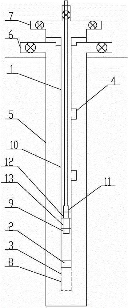
[0018] Example 1: The under-balanced tubing, snubbing gas lift, pumping, and pump inspection are combined as follows: The first step is to fix and install the tubing string 1 from top to bottom. In-line blowout preventer 2 and basket 3, fixedly install the valve holder in the oil pipe blowout preventer 2, install the valve in the valve holder, and install no less than one reverse gas lift valve in the middle of the oil pipe string 1. 4. Fix the pump seat 12 on the lower inner side of the tubing string 1, fix the pump sealer 13 at the lower end of the pump seat 12, and fix the pump seal valve on the pump sealer 13, fix the upper end of the casing 5 on the wellhead, and extract oil The four-way 6 is fixedly installed on the casing 5 above the wellhead, in which: the starting pressure of the reverse gas lift valve 4 is set to be greater than the pressure of the liquid column running into the well; the second step is to run the tubing string 1 into the casing In step 5, the upper ...
Embodiment 2
[0019] Embodiment 2: As an optimization of the above-mentioned embodiment, the blowout prevention device 2 in the tubing is a ball-throwing holding pressure open tubing constant-pressure float valve, the valve fixing seat is a valve core, and the valve is installed on the valve core. In the third step, Put a crappy ball into the ball-suppressing-open tubing constant-pressure float valve to block the spool diversion channel in the ball-squeezing-open tubing constant-pressure float valve, and inject into the tubing string 1 through the Christmas tree 7 The fluid is held in pressure, and the spool of the ball-throwing holding pressure open tubing constant pressure float valve and the valve on the spool are sent into the basket 3 together, and the tubing string 1 is connected to the well through the through hole 8 on the basket 3 to establish production aisle. The pitch holding pressure open tubing constant pressure float valve adopts the technology in the Chinese patent document ...
Embodiment 3
[0020] Embodiment 3: The difference from the above embodiment is that in the sixth step, after the overhaul of the sucker pump 11 is completed, the sucker pump 11 is fixedly installed at the lower end of the sucker rod 10, and the sucker pump 11 is fixedly installed at the lower part of the sucker rod 10 Open the pump core tube 9, and then lower the sucker rod 10 into the tubing string 1, the sucker pump 11 is seated on the pump seat 12, and then the sucker pump 11 and the pump seat 12 perform bumping operations, and turn on the pump while bumping the pump. The core tube 9 stabs the valve of the pump, and the valve of the pump is in an open state, so that the pump 11 and the pump 13 are communicated with the lower end of the tubing string 1, and a pumping channel is established for pumping operations.
PUM
 Abstract
Description
Claims
Application Information
 - R&D
- Intellectual Property
- Life Sciences
- Materials
- Tech Scout
- Unparalleled Data Quality
- Higher Quality Content
- 60% Fewer Hallucinations
Browse by: Latest US Patents, China's latest patents, Technical Efficacy Thesaurus, Application Domain, Technology Topic, Popular Technical Reports.
© 2025 PatSnap. All rights reserved.Legal|Privacy policy|Modern Slavery Act Transparency Statement|Sitemap|About US| Contact US: help@patsnap.com

