Underbalance tubing, no-killing gas lifting, shaft pumping and pump detecting combined method

An underbalanced and oil tubing technology, which is applied in the joint operation of pumping and pump inspection, snubbing gas lift, and underbalanced oil tubing, can solve problems such as operation cycle uplift, weakened reservoir protection effect, and blocked production channels. , to achieve the effects of improving competitiveness, maintaining the effect of increasing production capacity, and simplifying production operations

Active Publication Date: 2013-12-25
CNPC XIBU DRILLING ENG
View PDF6 Cites 5 Cited by
  • Summary
  • Abstract
  • Description
  • Claims
  • Application Information

AI Technical Summary

Problems solved by technology

[0004] The present invention provides a joint operation method of under-balanced tubing, snubbing gas lift, pumping transfer and pump inspection, which overcomes the shortcomings of the above-mentioned prior art, and can effectively solve the problem of unblocked production channels in the oil recovery process , operation cycle uplift and independent operations weaken the reservoir protection effect

Method used


Image

  • Underbalance tubing, no-killing gas lifting, shaft pumping and pump detecting combined method

Examples


Embodiment 1

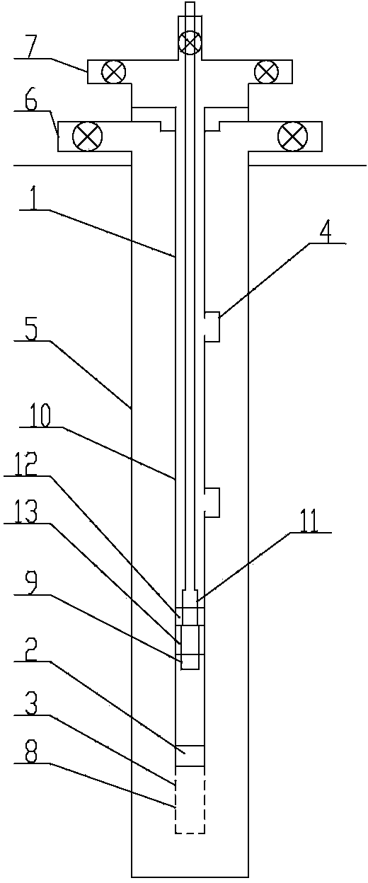
[0018] Embodiment 1: The joint operation method of under-balanced tubing, snubbing gas lift, pumping transfer and pump inspection is carried out as follows: first step, the bottom end of the tubing string 1 is fixed and installed sequentially from top to bottom Blowout preventer 2 and basket 3 in the oil pipe, the valve fixing seat is fixed in the blowout preventer 2 in the oil pipe, the valve is installed in the valve fixing seat, and no less than one reverse gas lift valve is fixed in the middle of the oil pipe string 1 4. Fix the pump seat 12 on the inner side of the lower part of the tubing string 1, fix the pump sealing device 13 at the lower end of the pump seat 12, and fix the pump sealing valve on the pump sealing device 13, and fix the upper end of the casing 5 on the wellhead, and the oil production The four-way 6 is fixedly installed on the casing 5 above the wellhead, wherein: the starting pressure of the reverse gas lift valve 4 is set to be greater than the liqu...

Embodiment 2

[0019] Embodiment 2: As an optimization of the above-mentioned embodiment, the blowout prevention device 2 in the oil pipe is a pressure-throwing open type oil pipe constant-pressure floating valve, the valve fixed seat is a valve core, and the valve is installed on the valve core. In the third step, to The pressure ball is put into the pressure-holding open type oil pipe constant pressure float valve of the pitching ball, and the ball is blocked by the pressure ball to block the diversion channel of the spool in the pressure-holding open type oil pipe constant pressure float valve of the pitching ball. The fluid is pressure-suppressed, and the spool and the valve on the spool of the ball-suppressed open-type tubing constant pressure float valve are sent to the basket 3 together, and the tubing string 1 is communicated with the well through the through hole 8 on the basket 3 to establish a production aisle. The pressure-suppressed open oil pipe constant-pressure float valve ...

Embodiment 3

[0020] Embodiment 3: The difference from the above embodiment is that in the sixth step, after the overhaul of the oil well pump 11 is completed, the oil well pump 11 is fixedly installed at the lower end of the oil well pump 10, and the bottom of the oil well pump 11 is fixedly installed Open the pump core pipe 9, and then lower the sucker rod 10 into the tubing string 1, the oil well pump 11 is seated on the pump base 12, and then the oil well pump 11 and the pump base 12 perform the operation of touching the pump, and the pump is opened at the same time as the operation of the pump The core tube 9 pokes the valve of the sealing pump, and the valve of the sealing pump is in an open state, so that the oil well pump 11 and the sealing device 13 communicate with the lower end of the tubing string 1 to establish an oil pumping channel for oil pumping operations.


PUM


Abstract

The invention relates to the technical field of underbalance well-completion practice and oil production operation, in particular to an underbalance tubing, no-killing gas lifting, shaft pumping and pump detecting combined method. The underbalance tubing, no-killing gas lifting, shaft pumping and pump detecting combined method is carried out according to the following step: a first step of sequentially and fixedly arranging an oil tube inner blowout preventer and a lifting basket at the bottom end of a tubing string from top to bottom, fixedly arranging a valve fixing seat in the oil tube inner blowout preventer and arranging a valve in the valve fixing seat. According to the invention, by fixedly arranging the oil tube inner blowout preventer at the bottom of the tubing string, not only can the tubing operation be successfully completed in the well completion stage, but also in the gas-lifting oil production process, a gas lifting drainage or production passage can be established, the tubing operation, the gas-lifting oil production operation, the oil pumping operation and the oil-well pump overhauling operation are tightly combined, the operation period is shortened, the production operation is simplified, a reservoir protection effect of an underbalance drilled well is reinforced and an oil / gas well can be timely put into production and is kept having an excellent capacity promoting effect, so that competitiveness of the underbalance technology is improved.

Description

Technical field [0001] The invention involves the field of well -finishing operations and oil collection operations. It is a joint method of arrears of balancing underlying oil pipes, non -pressed gas lifting, rotation and pumps. Background technique [0002] At present, when the well drilled by the underwriting technology is adopted at the end of the well, the oil pipe unilateral valve fixed valve is generally installed at the bottom of the oil pipe column to prevent the fluid in the well sprayed from the oil pipe from the oil pipe during the oil pipe.Install the reverse gas lifting valve in the appropriate position of the oil pipe column. After the oil pipe pillar is sealed, the inner passage of the oil pipe is opened to open the inner passage of the oil pipe to achieve the oil -liquid discharge or production channel.In the actual process, the existing device has a circular blind spot during the application process.After the lower drill to a certain well, there is a pressure di...

Claims


Application Information

Patent Timeline
Patent Type & Authority Applications(China)
IPC IPC(8): E21B43/00E21B33/03E21B47/008
Inventor 张彦龙杨勇胡挺吴振华孙新江宗泽斌
Owner CNPC XIBU DRILLING ENG
Why Eureka
Try Eureka