
Clutches used in fuel-efficient racing cars

A competitive racing car and clutch technology, which is applied to the racing field of energy-saving competitive competitions, can solve the problem that the volume and structure of the clutch cannot meet the requirements of energy-saving racing cars, and achieve the effects of simple structure, reduced energy consumption, and power separation.

Inactive Publication Date: 2015-10-14
谢利
View PDF6 Cites 0 Cited by
  • Summary
  • Abstract
  • Description
  • Claims
  • Application Information

AI Technical Summary

Problems solved by technology

[0004] There are many clutches commonly used now, but considering that the volume and structure of traditional clutches cannot meet the requirements of energy-saving racing cars, there is an urgent need for a clutch that adapts to the driving mode of energy-saving racing cars

Method used


Image

  • Clutches used in fuel-efficient racing cars
  • Clutches used in fuel-efficient racing cars
  • Clutches used in fuel-efficient racing cars

Examples


Embodiment 1

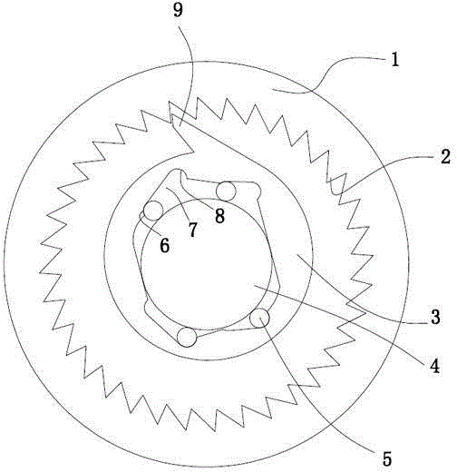
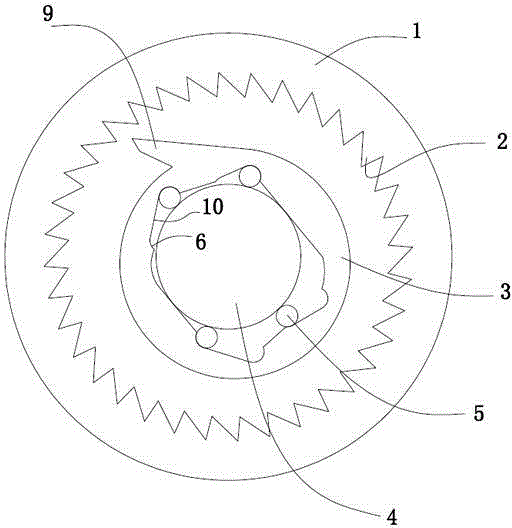
[0023] Embodiment 1: a kind of clutch that energy-saving racing car uses (referring to the attached figure 1 ), including a drive shaft 4, a drive disc 3 sleeved on the drive shaft, and a drive gear 3 outside the drive disc.

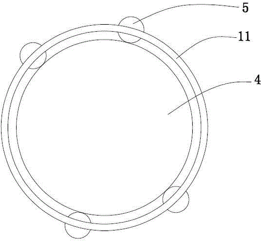
[0024] Four rollers 5 are fixedly installed by cage 11 on the outer periphery of driving shaft (see attached image 3 ), the inner ring of the driving gear is provided with internal teeth 2, and the driving disc is fixed with a transmission arm 9 that meshes with or separates from the internal teeth.

[0025] The inner wall of the drive disc is provided with an arc-shaped groove 7 at a position corresponding to the roller, and the roller and the arc-shaped groove constitute a radial movement drive mechanism for the drive disc to move radially relative to the driving shaft. The depth of the arc-shaped groove changes along the circumferential direction. The depth of the arc-shaped groove at the starting end within the range of the front 90° and rear 90° o...

Embodiment 2

[0028] Embodiment 2: A clutch used in energy-saving competitive racing cars. The outer periphery of the driving shaft is provided with an arc-shaped groove, and the inner hole wall of the driving disc is fixedly installed with rollers through a cage. The arc groove forms the start end and the end end along the rotation direction of the driving shaft, the bottom of the arc groove is a straight plane, and the depth of the start end of the arc groove within the range of the front 90° and rear 90° of the transmission arm is smaller than the end point The depth of the groove at the end, the depth of the groove at the starting end of the arc groove within the scope of another 180° on the drive disc is greater than the depth of the groove at the terminal end. A conical spring is arranged on the end surface of the arc-shaped groove where the depth of the groove is the largest, and the large diameter end of the conical spring is fixed to the end surface of the groove.

[0029] The roll...


PUM


Abstract

The invention relates to a clutch applied to an energy-saving competitive racing car. The clutch comprises a driving shaft and a driving gear with inner teeth, wherein a driving disc capable of radially moving relative to the driving shaft is sleeved on the driving shaft, a driving mechanism for driving the driving disc to radially move is arranged between the driving shaft and the driving disc, a transmission arm is fixed on the driving disc, and the transmission arm is meshed with or separated from the inner teeth when the driving disc radially moves. According to the clutch applied to the energy-saving competitive racing car, which is disclosed by the invention, the transmission arm and the driving gear are meshed and separated by radial offset of the driving disc, so that the power clutch is finished, the structure is simple, and the purpose of reducing the energy consumption is achieved.

Description

technical field [0001] The invention relates to the field of racing cars in energy-saving competitions, in particular to a clutch used in energy-saving racing cars. Background technique [0002] At present, energy conservation and environmental protection are the trend of industrial development, and the country is paying more and more attention to environmental protection issues. At the same time, energy consumption has also become a technical requirement at the national strategic level. The automobile is an important industrial pillar of a country. With the rapid development of the national economy, the automobile industry has been significantly promoted, and the number of vehicles per capita has also continued to increase. However, the ensuing energy consumption and air pollution have also become problems that the automobile industry needs to overcome. problem. The Honda Energy Saving Contest timely caters to the needs of the times to increase social awareness of energy c...

Claims


Application Information

Patent Timeline
Patent Type & Authority Patents(China)
IPC IPC(8): F16D41/18F16D41/066
Inventor 吴锋祥
Owner 谢利
Learn More