Image blur correction apparatus and imaging apparatus

A blur correction and image technology, applied in installation, optics, instruments, etc., can solve the problems of complex structure and increase in the number of parts, and achieve the effect of simple structure, reduced number, and reduced size

Inactive Publication Date: 2013-12-18
SONY CORP
View PDF1 Cites 0 Cited by
  • Summary
  • Abstract
  • Description
  • Claims
  • Application Information

AI Technical Summary

Problems solved by technology

[0007] However, in the image blur correction device described in JP H7-274056A, two gimbal mechanisms are provided for rotating the lens unit in the yaw direction and the pitch direction, so that the number of parts is disadvantageously increased and the configuration is changed due to their presence. more complicated

Method used


Image

  • Image blur correction apparatus and imaging apparatus
  • Image blur correction apparatus and imaging apparatus
  • Image blur correction apparatus and imaging apparatus

Examples


no. 1 example )

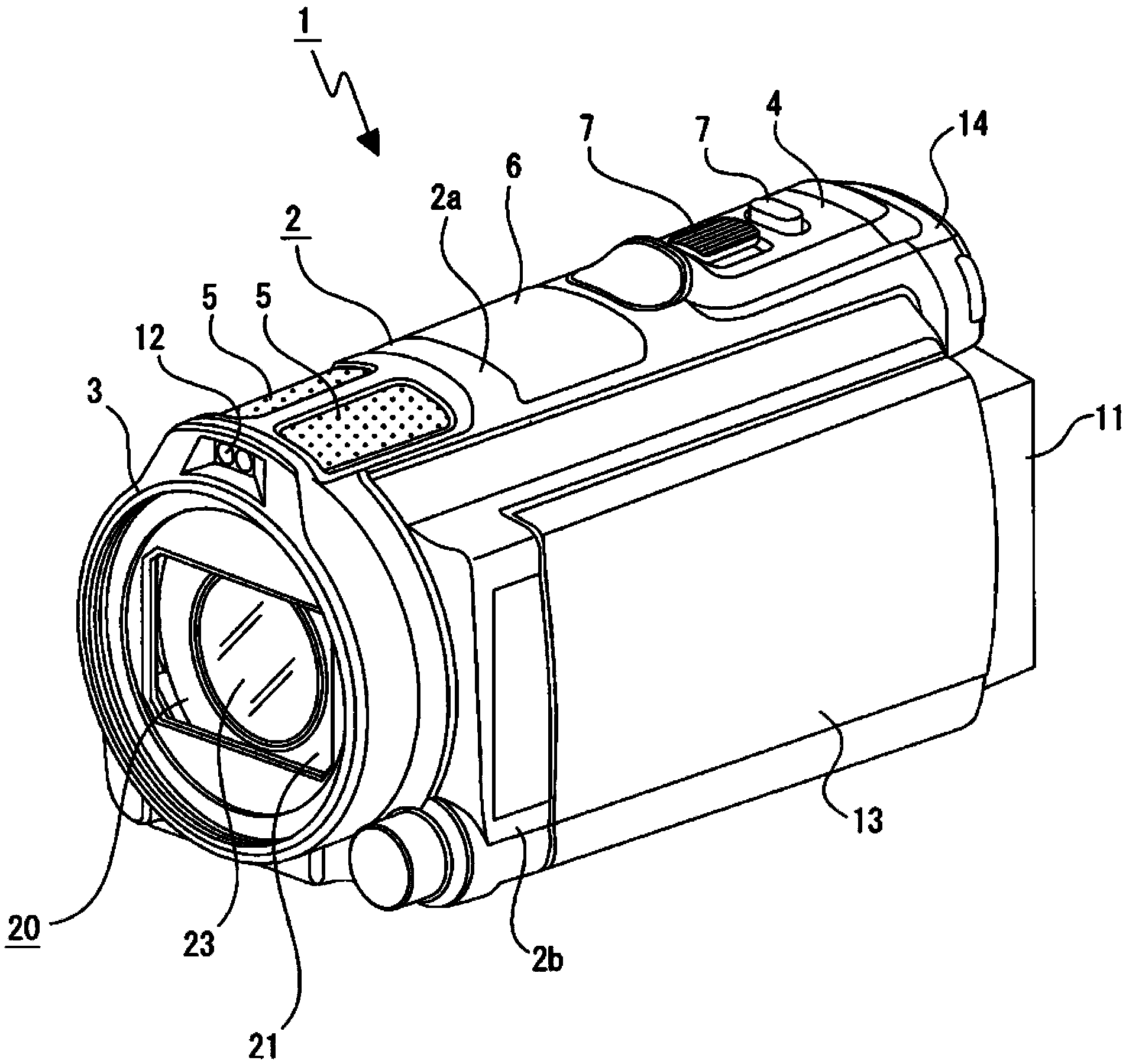
[0090] The image blur correction device 20 according to the first embodiment of the present technology will now be described (refer to Figure 1 to Figure 9 ).

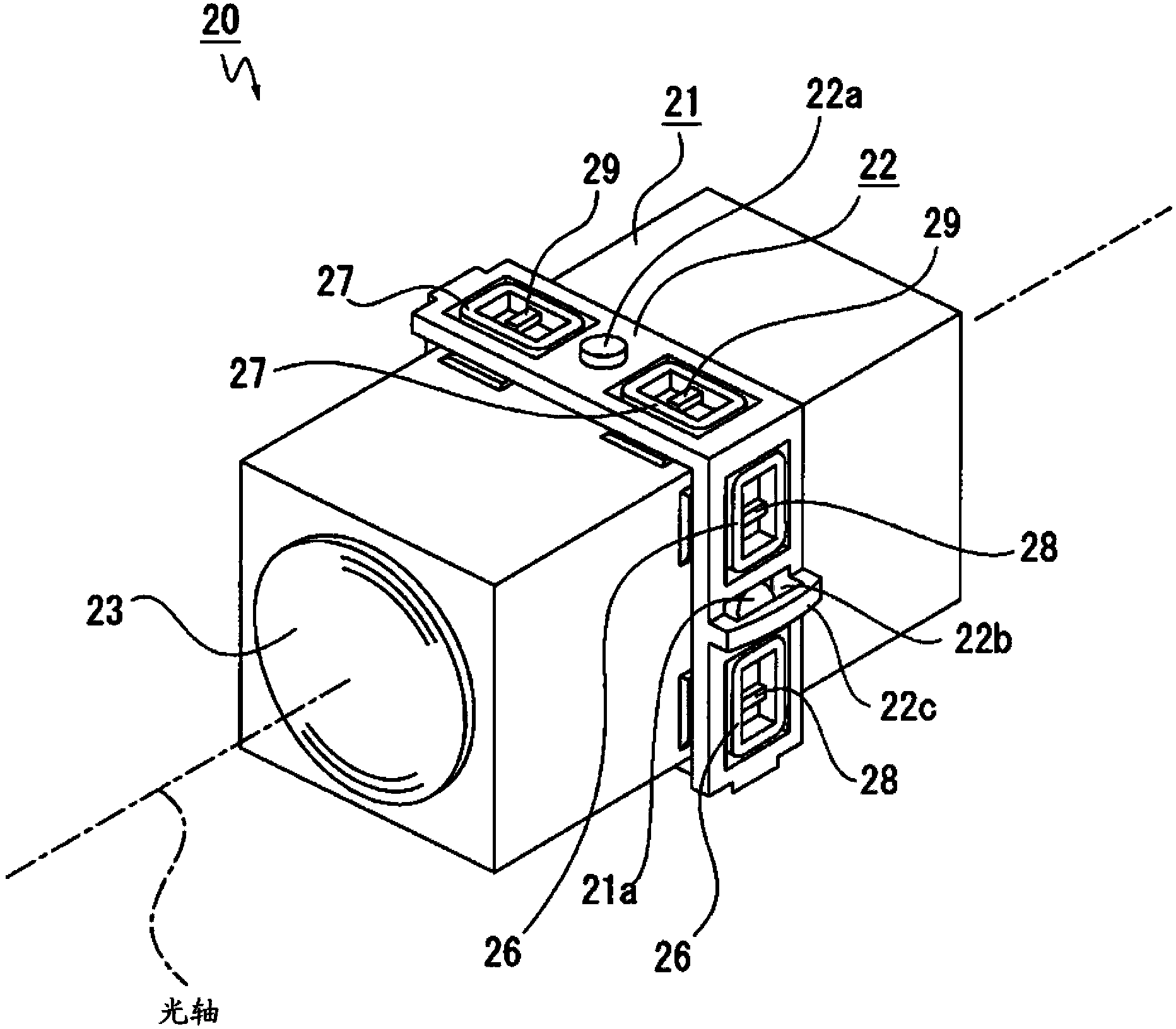
[0091] The image blur correction device 20 is arranged in the housing 2 (refer to figure 1 ). The image blur correction device 20 has: a lens unit 21 and a fixing member 22 supporting the lens unit 21 (refer to Figure 3 to Figure 5 ).

[0092] The lens unit 21 is formed in a shape extending in the optical axis direction, for example, a substantially rectangular shape. A lens group or a plurality of lenses in an array are arranged in the lens unit 21 along the optical axis direction. The lens 23 is referred to as a "front lens" and is disposed on the most front side (object side).

[0093] In the lens unit 21, first rotation shafts 21a and 21a protruding outward are provided on left and right faces, respectively, and first supporting grooves 21b and 21b opened outward are formed on upper and lower faces, respecti...

no. 2 example )

[0141] An image blur correction device 20C according to a second embodiment of the present technology will now be described (refer to Figure 15 to Figure 17 ).

[0142] It should be noted that an image blur correction device 20C shown below differs from the image blur correction device 20 described above only in that the lens unit can also be turned in a third direction in addition to the first direction and the second direction. Therefore, with regard to the image blur correction device 20C, only components different from the image blur correction device 20 will be described in detail. Other components are denoted with the same reference numerals as similar components in the image blur correction device 20, and descriptions thereof are omitted.

[0143] The image blur correction device 20C has: a lens unit 21C, and a fixing member 22C supporting the lens unit 21C (refer to Figure 15 with Figure 16 ).

[0144] The lens unit 21C is formed in a shape extending in the opti...


PUM


Abstract

Provided is an image blur correction apparatus including a lens unit that configured to include at least one lens, and configured to turnable in a first direction which is a direction about a first supporting axis that is orthogonal to a light axis of the lens with respect to an outer housing, and in a second direction which is a direction about a second supporting axis that is orthogonal to the light axis and the first supporting axis, a fixed member configured to turnably support the lens unit in the first direction and the second direction, a first drive unit configured to turn the lens unit in the first direction, and a second drive unit configured to turn the lens unit in the second direction.

Description

technical field [0001] The present technology relates to the technical fields related to image blur correction devices and imaging devices. More specifically, the present technology relates to providing a first rotation shaft and a second rotation shaft on a lens unit and a fixing member, respectively, and forming a first support groove for supporting the second rotation shaft and supporting the first rotation shaft on the lens unit, respectively. The technical field that the first supporting groove makes the structure simpler and more compact. Background technique [0002] In imaging devices such as video cameras and still cameras, image blur correction means may be provided for correcting image blur by moving a lens in a direction orthogonal to the optical axis direction. [0003] The image blur correction device provided in such an imaging device may be configured such that the lens unit having the lens is rotated in a first direction with respect to the housing about a ...

Claims


Application Information

Patent Timeline
Patent Type & Authority Applications(China)
IPC IPC(8): G02B7/02
CPCG02B27/646G03B2205/0023
Inventor 中山立幸
Owner SONY CORP
Why Eureka
Try Eureka