Rotating-magnetic-field generator

A technology of rotating magnetic field and generator, which is applied in the direction of using variable magnetic field and permanent magnet generated by mechanical movement, which can solve the problems of high production cost and many structural parts of rotating magnetic field generator, so as to reduce structural parts and reduce production cost effect

Active Publication Date: 2013-12-18
安吉司润磁性材料股份有限公司
View PDF5 Cites 0 Cited by
  • Summary
  • Abstract
  • Description
  • Claims
  • Application Information

AI Technical Summary

Problems solved by technology

The rotating magnetic field generator has many structural components, mainly the motor, resulting in high production costs

Method used


Image

  • Rotating-magnetic-field generator
  • Rotating-magnetic-field generator
  • Rotating-magnetic-field generator

Examples


Embodiment 1

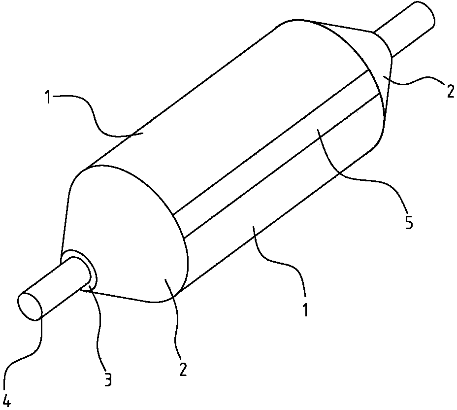
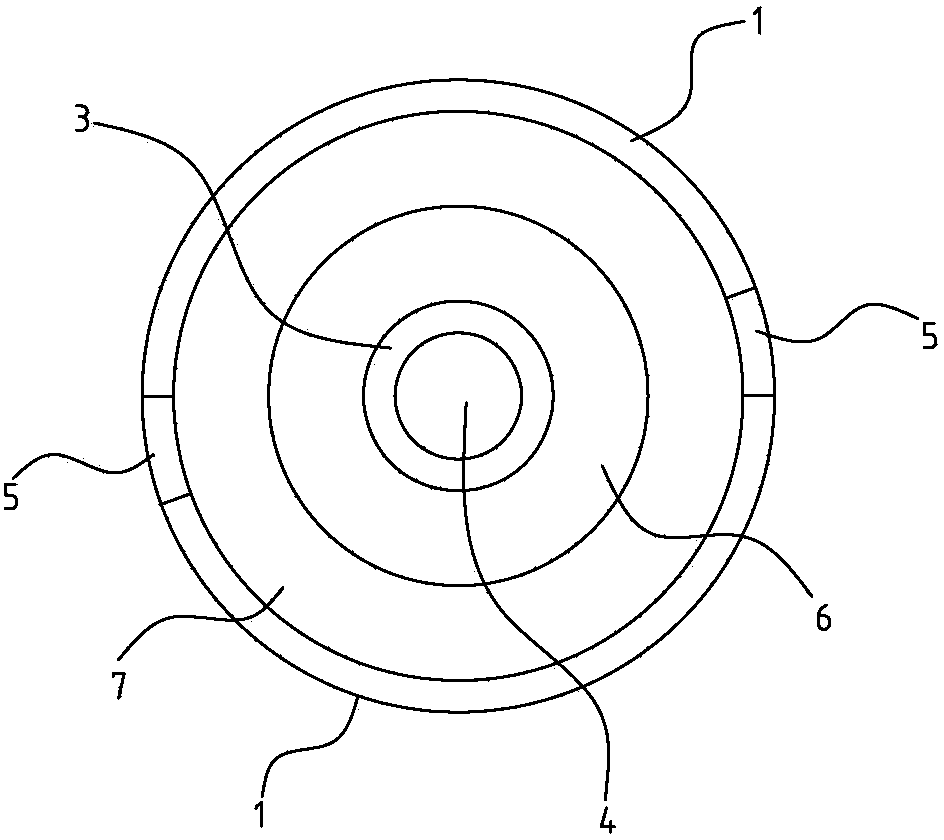
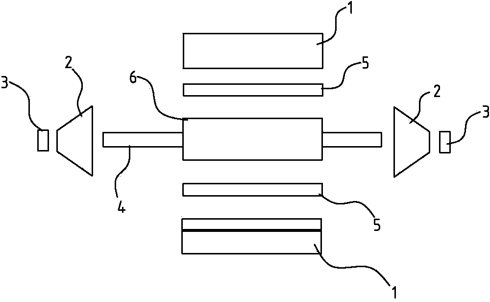
[0017] Such as Figures 1 to 3 As shown, a rotating magnetic field generator includes a power source and a magnetic field generator. In this embodiment, the magnetic field generating body is composed of two arc-shaped permanent magnet units 1 in a circle, and a separator 5 is arranged between the two permanent magnet units 1 to separate them, and the two permanent magnet units 1 The magnetic poles of the magnet unit 1 are reversed. The interior of the magnetic field generating body is a hollow structure to form an internal magnetic field space 7, and a stator 6 is arranged in the internal magnetic field space 7, and the stator 6 is composed of a shaft core 4, a silicon steel sheet (not marked) disposed on the shaft core 4, and a Composed of coil windings (not marked) on a silicon steel sheet. Both ends of the magnetic field generating body are provided with end caps 2, and the end caps 2 are provided with bearings 3, and the bearings 3 are sleeved on the shaft core 4 of the ...

Embodiment 2

[0019] Such as figure 1 , 4 As shown, a rotating magnetic field generator includes a power source and a magnetic field generator. In this embodiment, the magnetic field generating body is formed by four arc-shaped permanent magnet units 1 forming a circle, adjacent permanent magnet units 1 are separated by separators 5, and adjacent permanent magnet units The magnetic poles of the magnet unit 1 are reversed. The inside of the magnetic field generating body is a hollow structure to form an internal magnetic field space 7, and a stator 6 is arranged in the internal magnetic field space 7, and the stator 6 is composed of a shaft core 4, a silicon steel sheet arranged on the shaft core 4, and a coil arranged on the silicon steel sheet composed of windings. Both ends of the magnetic field generating body are provided with end caps 2, and the end caps 2 are provided with bearings 3, and the bearings 3 are sleeved on the shaft core 4 of the stator 6, that is, the stator 6 can rota...


PUM


Abstract

A rotating-magnetic-field generator comprises a power source and a magnetic field generator body. The magnetic field generator body is composed of an even number of arc-shaped permanent magnet units enclosing in a circle, and magnet poles of the neighboring permanent magnet units are opposite. An inner magnet space provided with a stator is formed in the magnetic field generator body, the stator is composed of a shaft core, a silicon steel sheet arranged on the shaft core and a coil winding arranged on the silicon steel sheet, and the stator and the magnetic field generator body jointly form the power source. Magnetic field lines generated by all the permanent magnet units to the inner magnet space provide an excitation magnetic field to the power source, when the coil winding of the stator into a current, the stator is fixed, and then the magnetic field generator body rotates around the stator. When the magnetic field generator body rotates, each permanent magnet unit launches the magnetic fields outwardly, and the magnetic field lines rotate with the magnetic field generator body to form a rotating magnetic field. By the arrangement, structural parts of the rotating-magnetic-field generator can be reduced, and production cost can be effectively lowered.

Description

technical field [0001] The invention relates to a magnetic field generator, in particular to a rotating magnetic field generator. Background technique [0002] With the continuous development of medical technology, magnetic fields are more and more widely used in medical treatment, health care and daily life, especially rotating magnetic fields. Rotating magnetic fields are generally generated by rotating magnetic field generators. Thanks to the application of rotating magnetic fields, the types of rotating magnetic generators are also diversified. A kind of rotating magnetic field generator such as Chinese patent publication number is 101630563, and it comprises bracket, is provided with motor on the bracket, is provided with lower turntable on the output shaft of motor, is provided with even number of permanent magnets on the lower turntable, adjacent permanent magnets are far away from One end of the lower turntable has opposite magnetic poles, an upper turntable is arra...

Claims


Application Information

Patent Timeline
Patent Type & Authority Applications(China)
IPC IPC(8): H01F7/02A61N2/12
Inventor 柴立民李帅李光其王文光
Owner 安吉司润磁性材料股份有限公司
Why Eureka
Try Eureka