
Anti-crack device and process for bearing conical rolling body

A rolling element and anti-crack technology, which is applied in the field of bearing manufacturing, can solve the problems of unsatisfactory product quality, bearing reliability, blanking uniformity, white ash thickness, and production efficiency that cannot adapt to the operation mode. The effect of saving equipment occupancy rate and reducing scrap rate

Inactive Publication Date: 2013-12-25
张军
View PDF7 Cites 0 Cited by
  • Summary
  • Abstract
  • Description
  • Claims
  • Application Information

AI Technical Summary

Problems solved by technology

[0003] How to solve this problem has become a problem that has plagued more than 20 years. In the past, the method of using lime ash to prevent cracks was used to slow down the cooling rate, but the uniformity of the blanking and the thickness of the lime are difficult to control, and the lack of measures Based on scientific basis, the effect cannot meet the requirements, and the crack rate accounts for more than 20%, which is a serious loss. The problem of crack research for this specification product is becoming more and more prominent and needs to be solved urgently
[0004] At present, the international military struggle is becoming more and more complicated. The 2007112X-269A / 3 conical rolling element pressure crack can not meet the requirements of product quality and bearing reliability by relying entirely on post-production manual selection, and the production efficiency can not adapt to the current operation mode. Guarantee 100% No cracks No means of technical control

Method used


Image

  • Anti-crack device and process for bearing conical rolling body
  • Anti-crack device and process for bearing conical rolling body
  • Anti-crack device and process for bearing conical rolling body

Examples


Embodiment 1

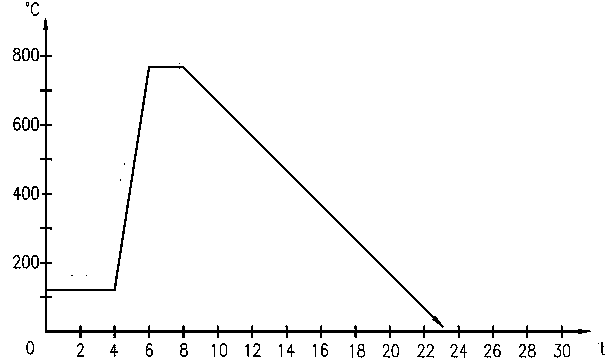
[0021] After the rolling body is pressed by the roller automatic cold heading machine, the temperature of the rolling body is 110°C, and it flows into the mesh box from the material channel. At this time, the oil is heated through the adjustment of the thermostat. When the temperature reaches 130°C, the shaker is started. Under the action of the shaker, the temperature of the rolling body and the temperature of the liquid oil are balanced. After 4 hours, until the mesh box is full, the rolling body is lifted and dried, and dried quickly to prevent high-temperature combustion during annealing, and then Transfer to heat treatment and annealing to stabilize the structure, heat for 2 hours and the temperature rises to 770°C, hold for 2.5 hours and then cool to room temperature with the furnace, so far the whole process of structure stabilization is completed, and then the post-processing work such as machining is performed.


PUM


Abstract

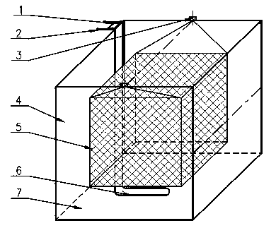
The invention relates to an anti-crack device and process for a bearing conical rolling body, and the device and the process are used for bearings of military products and belong to the technical field of manufacturing of bearings. The anti-crack device comprises a thermostat, a conductor, a single-control shaker, an outer box body, a reticular box body and a heater. The process comprises the following steps: briquetting, performing an anti-crack process step and performing heat treatment annealing. The conical rolling body is briquetted through an ordinary method and then enters the anti-crack device, when the conical rolling body flows into the reticular box body from a material path after being briquetted, the temperature of the rolling body and the temperature of liquid oil can achieve the balance under the action of the shaker till the reticular box body is fully pressed, then the conical rolling body is lifted up for draining and fast wiped dry for preventing high-temperature combustion during annealing, and then the conical rolling body is transferred into a heat treatment annealing stable texture so as to be conductive to controlling and strengthening the quality of the conical rolling body; the problems that cracks are produced by briquetting and miss points are produced by relying on subsequent flaw detection and selection are solved, the key point is that the strict requirements of the military products for quality are solved, the guarantee of the military products is reliable and powerful, and the labor force in flaw detection is simultaneously saved; the working efficiency is high, and the cost consumed by production is low.

Description

[0001] Technical field The present invention relates to anti-crack equipment and technology for bearing rolling body pressing, in particular to anti-crack equipment and technology for bearing tapered rolling body, which is used for military bearings and belongs to the technical field of bearing manufacturing. Background technique [0002] Military product bearing 2007112X-269A / 3 tapered rolling element in Z31-25 roller automatic cold heading machine compression molding process, due to the high temperature generated by high-strength extrusion molding, the physical properties of the material change, and the instantaneous volume of the mold exits after compression molding Slight expansion, and rapid cooling and contraction under the action of air temperature at the same time, the physical properties of the material change again. At this time, the temperature difference caused by the local difference in material density during the extrusion process and the local velocity unevenness ...

Claims


Application Information

Patent Timeline
Patent Type & Authority Applications(China)
IPC IPC(8): C21D8/00C21D9/36
Inventor 王茂庚李云孔达李财林于晓岩孟凡超纪恩杰王兴国邹清和
Owner 张军
Learn More