
Core valve energy storing type hydraulic down-the-hole hammer

A technology of down-the-hole hammer and core valve, which is used in drilling equipment, earth-moving drilling, driving device for drilling in wellbore, etc. Function loss and other problems, to achieve the effect of timely and accurate valve switching, not easy to collect sand, and small caliber

Active Publication Date: 2015-04-29
昆明国经液压锤制造有限公司
View PDF7 Cites 0 Cited by
  • Summary
  • Abstract
  • Description
  • Claims
  • Application Information

AI Technical Summary

Problems solved by technology

However, because the sleeve valve in the valve control mechanism also has the function of the cylinder liner when the piston is hydraulically lifted, it is a composite function valve control mechanism, so the function of the valve is vulnerable to the inferior quality of solid particles in the process of lifting the hammer. The interference of the working fluid or the over-tight seal makes the hammer work unstable. The impact is stopped halfway and the valve is closed but not completely closed after the impact is stopped. The drainage resistance increases significantly, and the working fluid flows from the valve. The speed of spraying from the gap between the valve seat and the valve seat is dozens of times the normal liquid discharge speed, and the high-speed sprayed working medium containing mud and sand will quickly erode the closed surface between the valve and the valve seat, resulting in the loss of valve function and other failures; the above problems It restricts the application range of the energy storage hydraulic DTH hammer; the key to solving the above problems is to develop a valve control mechanism that is completely free from the interference of the hammer lifting process.

Method used


Image

  • Core valve energy storing type hydraulic down-the-hole hammer
  • Core valve energy storing type hydraulic down-the-hole hammer
  • Core valve energy storing type hydraulic down-the-hole hammer

Examples


Embodiment 1

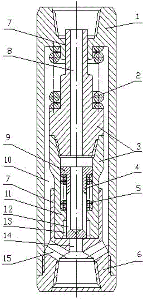
[0030] Example as figure 1 Shown: The down-the-hole hammer consists of the shell (1), hammer spring (2), hammer body (3) composed of upper hammer body and lower hammer body, core valve (4), valve spring (5), lower joint (6) Composition; between the shell (1) and the lower joint (6) and between the upper hammer body and the lower hammer body are connected by threads, the hammer spring (2) is set on the upper and middle sections of the upper hammer body, the core valve (4) and Valve spring (5) is contained in the inner chamber of lower hammer. The valve spring (5) is set outside the core valve (4), between the ring-shaped big head (9) on the top of the core valve and the step (11) in the inner cavity; the upper part of the upper hammer body and the shell are dynamically sealed (7), The lower part of the lower hammer body and the cylindrical inner wall of the upper part of the lower joint are dynamically sealed (7); the working fluid enters from the upper end of the casing (1), ...

Embodiment 2

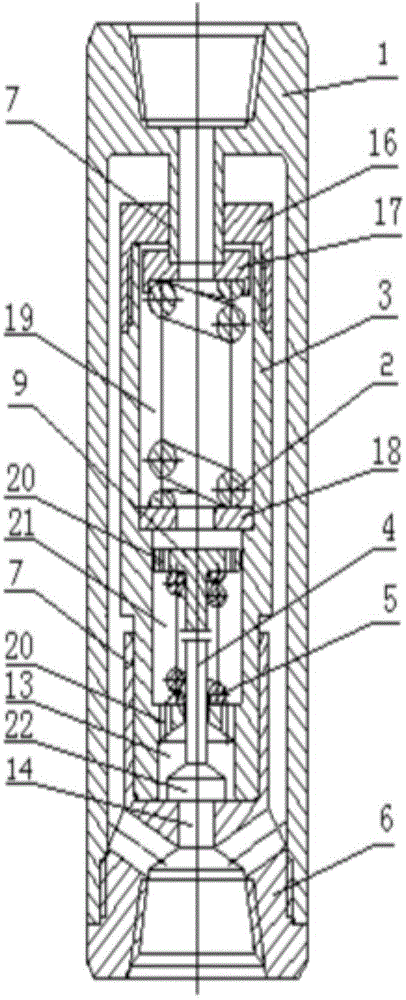
[0032] Example two such as figure 2 Shown: the down-the-hole hammer consists of a shell (1), an end cover (16), an upper spring seat (17), a hammer body (3), a hammer spring (2), a lower spring seat (18), a core valve (4), The valve spring (5) and the lower joint (6) are composed; between the shell (1) and the lower joint (6) and between the end cover (16) and the hammer body (3) are connected by threads, and the hammer spring (2) is installed In the hammer body upper cavity (19), the core valve (4) runs through the hammer body middle cavity (21) and the hammer body lower cavity (13), and the valve spring (5) is sleeved in the middle section of the core valve (4). Between the ring-shaped big head (9) on the top of the core valve and the step of the middle cavity of the hammer body (21); between the upper part of the casing (1) and the end cover (16) and between the lower section of the hammer body (3) and the lower joint ( 6) The cylindrical inner walls of the upper section ...

Embodiment 3

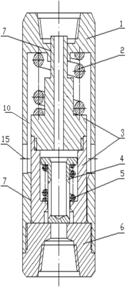
[0035] Embodiment three such as image 3As shown; the down-the-hole hammer is composed of the shell (1), the hammer spring (2), the hammer body (3), the core valve (4), the valve spring (5), and the lower joint (6) composed of the upper hammer body and the lower hammer body ; Both the shell (1) and the lower joint (6) and between the upper hammer body and the lower hammer body are rigidly connected, the structure and installation position of the hammer spring (2), core valve (4) and valve spring (5) Both are exactly the same as in Example 1; the upper part of the upper hammer body and the outer casing are dynamically sealed (7), and the lower part of the lower hammer body and the lower part of the outer casing are also dynamically sealed (7); the working fluid enters from the upper end of the outer casing (1). The drain hole (14) in the lower joint (6) is discharged, and the working fluid flow channel between them is exactly the same as that in Embodiment 1. The difference in...


PUM


Abstract

The invention discloses a core valve energy storing type hydraulic down-the-hole hammer. The lower portion of an outer shell (1) is in rigid connection with a lower connector (6), an upper hammer body and a lower hammer body in the outer shell (1) are in rigid connection, the upper segment and the middle segment of the upper hammer body are sleeved with hammer springs (2), a core valve (4) and a valve spring (5) are assembled in an inner cavity in the lower hammer body, the valve spring is arranged between an annular large head (9) of the top of the core valve and a step (11) of an inner cavity in the lower hammer body, the lower connector (6) is divided into an upper segment and a lower segment, the upper segment is in a cylinder shape, the bottom of the cylinder is a hammering face, a liquid draining hole (14) is formed in the center of the lower segment, the lower segment is communicated with a bottom cavity with an inner thread through the liquid draining hole, and the lower hammer body, the core valve, the valve spring and the hammering face of the lower connector form a core valve type valve control mechanism, wherein the core valve, the valve spring and the lower connector are installed in the lower hammer body. The core valve energy storing type hydraulic down-the-hole hammer can overcome defects in a valve control mechanism in the prior art, and the valve control mechanism of the energy storing type hydraulic down-the-hole hammer is not interfered by the hammer lifting process.

Description

technical field [0001] The invention relates to the field of drilling machinery, in particular to a core-valve energy-storage hydraulic down-the-hole hammer mainly used in the percussion rotary drilling technology of rock core drilling, water wells, oil drilling and mine drilling engineering. Background technique [0002] Hydraulic down-the-hole hammer has multiple action principles such as positive action, reverse action, double action and compound action. The energy-storage hydraulic down-the-hole hammer is a reaction type, for example: the energy-storage hydraulic down-the-hole hammer with the patent number ZL200910094971.6. [0003] The energy-storage hydraulic down-the-hole hammer has the advantages of simple structure, high energy utilization rate, small required working medium flow rate, reduced working hydraulic pressure, relatively large impact energy, adjustable frequency, flow rate from small to large within the rated working flow range, and working hydraulic press...

Claims


Application Information

Patent Timeline
Patent Type & Authority Patents(China)
IPC IPC(8): E21B4/14
Inventor 刘国经
Owner 昆明国经液压锤制造有限公司
Learn More