Back projection illuminating device

A lighting device and rear projection technology, which is applied in the direction of lighting devices, fixed lighting devices, lighting device components, etc., can solve the problems of human eye injury and discomfort, and achieve the goals of avoiding direct sunlight, reducing heat dissipation, and low energy consumption. Effect

Inactive Publication Date: 2013-12-25
WUXI TONGMING TECH
View PDF6 Cites 0 Cited by
  • Summary
  • Abstract
  • Description
  • Claims
  • Application Information

AI Technical Summary

Problems solved by technology

[0002] Lighting makes life more colorful, and bright lights make people's lives more beautiful. As people's taste in life becomes higher and higher, the requirements for lighting are also increasing. Various lights, all kinds of All kinds of lighting fixtures are the product of people's pursuit of a better life, but from beginning to end, people's constant pursuit is to make efforts in heat dissipation, light intensity, and appearance, but even so, existing lighting devices still have defects , while people consider increasing the brightness of the light, they ignore a problem. The increase of the light intensity will inevitably bring about the problem that the human eye will feel extremely uncomfortable when it is exposed to the light. It will cause damage to the human eye. Therefore, while continuously increasing the light intensity, the user's experience is also something that the designer needs to consider, and it needs to be placed at the top of the design factor.

Method used


Image

  • Back projection illuminating device
  • Back projection illuminating device

Examples


Embodiment Construction

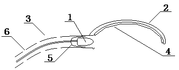
[0017] The specific implementation manners of the present invention will be further described in detail below in conjunction with the accompanying drawings.

[0018] Such as figure 1 As shown, the present invention designs a rear projection lighting device, which includes a light source 1, a top cover 2 and a communication pipe 3 connected at both ends, one end of the communication pipe 3 is connected to the edge of the top cover 2, and the communication pipe 3 is the The pipe opening on the end faces the inner surface of the top cover 2, and the light source 1 is powered by an external power supply through the Unicom pipeline 3 through the power line; it also includes a reflective mirror 4 arranged on the inner surface of the top cover 2, and the reflection of the reflective mirror 4 The surface points below the inner surface of the top cover 2, the light source 1 is arranged in the pipe at the end of the communication pipe 3 connected to the edge of the top cover 2, and the ...


PUM


Abstract

The invention relates to a back projection illuminating device, which comprises a light source (1), a top cover (2), a communicating pipeline (3) and a reflecting mirror surface (4), wherein the two ends of the communicating pipeline (3) are cut through; one end of the communicating pipeline (3) is connected with the edge of the top cover (2); a pipeline port in the end part of the communicating pipeline (3) faces the inner side face of the top cover (2); the light source (1) is externally connected with a power supply through a power wire and the communicating pipeline (3) to supply power; the reflecting mirror surface (4) is formed on the inner surface of the top cover (2); the reflecting surface of the reflecting mirror surface (4) points to the lower side of the inner surface of the top cover (2); the light source (1) is arranged in a pipeline on the end part of the communicating pipeline (3) connected with the edge of the top cover (2); the illuminating direction of the light source (1) points to the inner side face of the top cover (2). According to the reflection principle, irradiation light rays can be softened via the back projection illuminating device; the back projection illuminating device has a very large market application prospect and high economic value.

Description

technical field [0001] The invention relates to a rear projection lighting device. Background technique [0002] Lighting makes life more colorful, and bright lights make people's lives more beautiful. As people's taste in life becomes higher and higher, the requirements for lighting are also increasing. Various lights, all kinds of All kinds of lighting fixtures are the product of people's pursuit of a better life, but from beginning to end, people's constant pursuit is to make efforts in heat dissipation, light intensity, and appearance, but even so, existing lighting devices still have defects , while people consider increasing the brightness of the light, they ignore a problem. The increase of the light intensity will inevitably bring about the problem that the human eye will feel extremely uncomfortable when it is exposed to the light. It will cause damage to human eyes. Therefore, while continuously increasing the light intensity, the user's experience is also somethi...

Claims


Application Information

Patent Timeline
Patent Type & Authority Applications(China)
IPC IPC(8): F21S8/00F21V7/00F21V29/00F21Y101/02F21V29/15F21V29/83F21Y115/10
Inventor 姚迎宪
Owner WUXI TONGMING TECH
Why Eureka
Try Eureka