Sphere structure

a technology of spheres and spheres, applied in lighting applications, lighting and heating apparatus, instruments, etc., can solve the problems of only applying balls, manufacturing difficulties and costs, and poor environmental protection effect of external light sources to provide sufficient light to the sport field, so as to prevent damage to the outside of the sphere, easy assembly of light guiding modules, and easy assembly

Active Publication Date: 2016-09-22
LIN WEI HUNG
View PDF6 Cites 7 Cited by
  • Summary
  • Abstract
  • Description
  • Claims
  • Application Information

AI Technical Summary

Benefits of technology

[0008]In sum, it is known that the modified sphere structure has the containing space interconnecting with the light releasing space of the groove, allowing the light source module to be safely disposed within the sphere to avoid the overpower of a hit and the light releasing space and the light guiding member in the light releasing space can guide light coming from the light source that passes through the light releasing space and evenly lead the light to the whole groove and further to the outside of the sphere from the groove. Damaging impact can be prevented, and light transmission to the outside of the sphere can be ensured without dragging the illumination effect. The structure of the above-mentioned containing space and light interconnected to the releasing space of the groove allows the assembling of the light guiding module to be easier, the complexity of manufacturing to be prevented and the unnecessary costs to be deceased.

Problems solved by technology

However, utilization of an external light source to provide sufficient light to the sport field is not good for environment protection and also not cost saving.
However, these ball products mostly merely have some illuminating decorations or fluorescence elements simply disposed on the surface of the ball body and have no anti-collision mechanism formed thereon.
When a collision occurs, damages and failures to the ball result and such balls can only be applied for being play things, instead of being applied for practicing or throwing with heavy strength.
Even if such ball products were made with hit-improved efforts, they are basically made with a complex structure, resulting in manufacturing difficulties and costs.

Method used


Image

  • Sphere structure
  • Sphere structure
  • Sphere structure

Examples


first embodiment

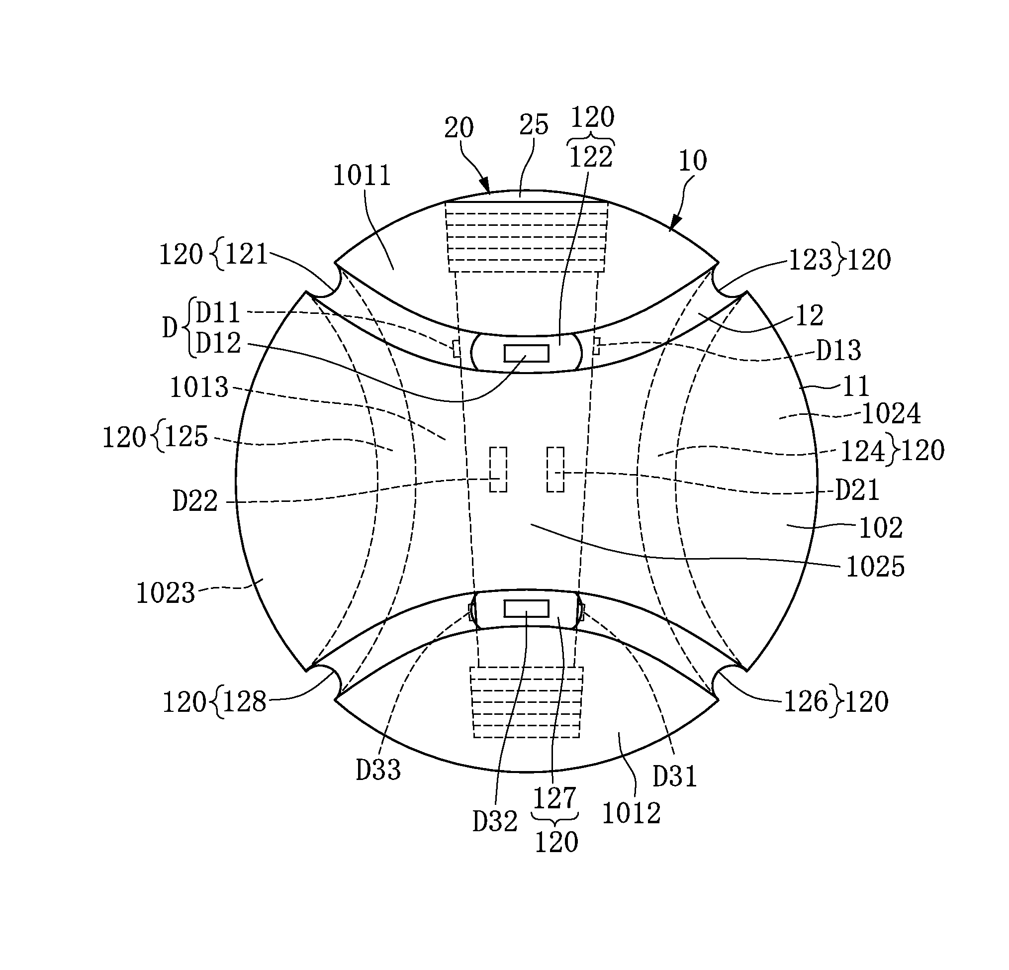
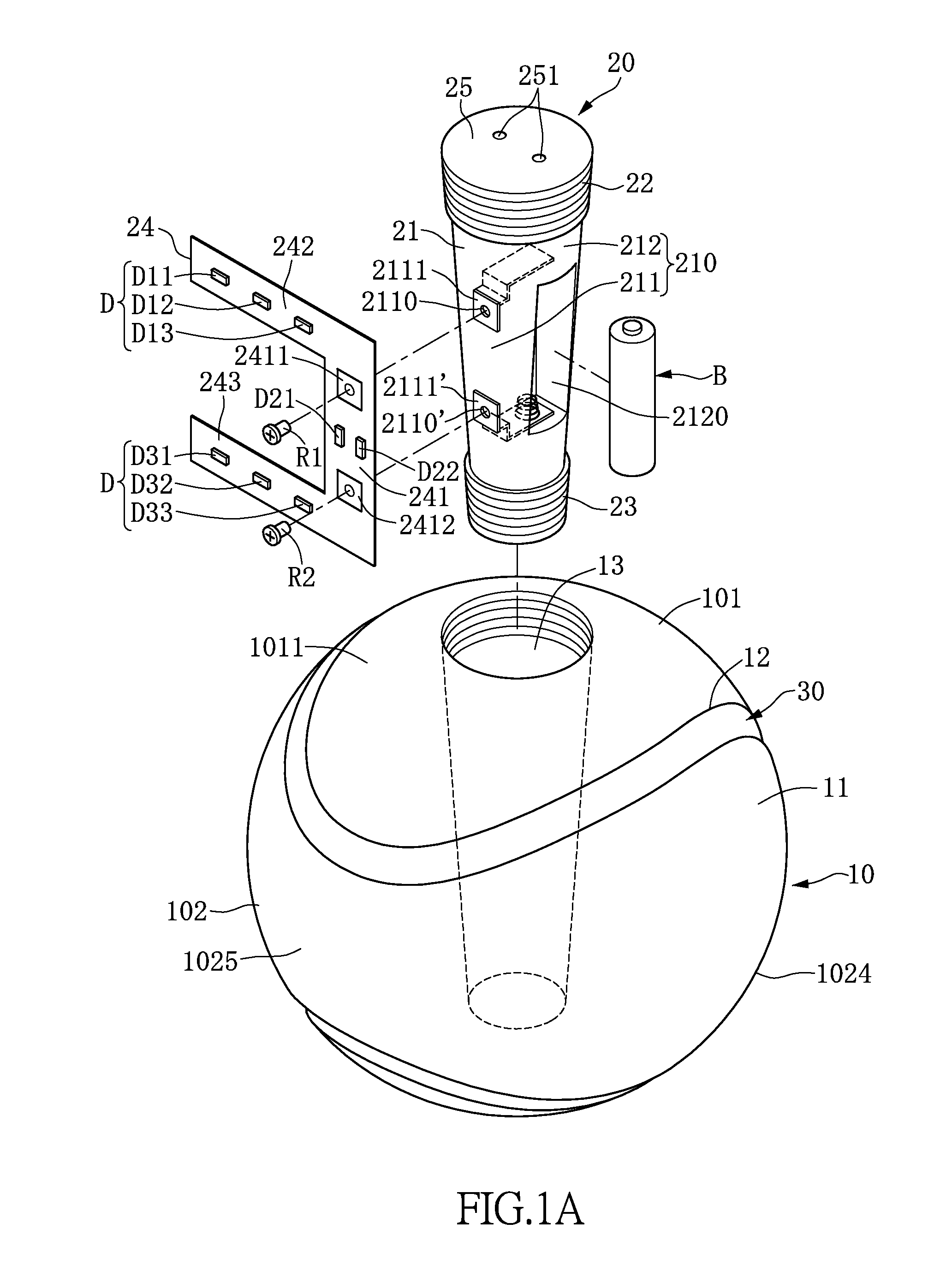
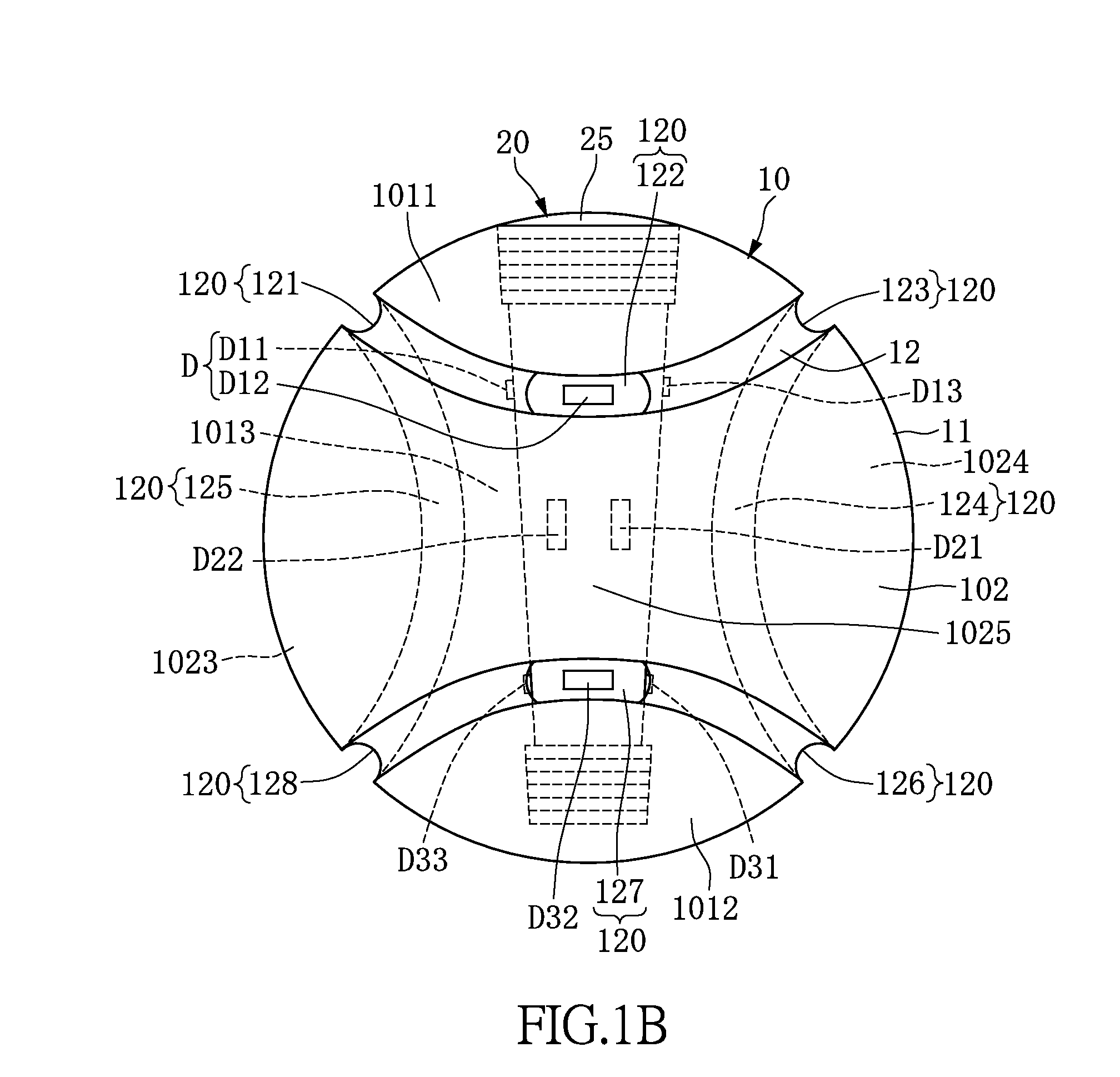
[0029]Please refer to FIGS. 1A and 1B. The present disclosure provides a modified sphere structure including: a sphere body 10, a light source module 20 and a light guiding member 30. A groove 12 is formed on the surface 11 of the sphere body 10 along a distribution path (label not shown). The light source module 20 is disposed in a containing space 13 formed from the surface 11 of the sphere body 10 to the inside of the sphere body 10. Please refer to FIG. 1C. The FIG. 1C is a schematic diagram of cross-section view of the first upper light emitting diode D11, an example, illustrated in the FIG. 1B. The groove 12 is connected to the containing space 13 to together define a light releasing space 120. The light releasing space 120 receives the light emitted from the light emitting diodes D of the light source module 20. Please refer to FIGS. 1A, 1C and 1D. The light guiding member 30 fills in the light releasing space 120 or even the whole groove 12. Thus, the light emitted from the ...

second embodiment

[0041]The main difference of the second embodiment to the first embodiment is that the light source module being used is different. Please refer to FIG. 2 which illustrates the light source module 20a belonging to the second embodiment. The light source module 20a includes a luminescence column 21a, an upper thread portion 22a and a lower thread portion 23a. The luminescence column 21a has a diameter decreased from an upper end of the luminescence column 21a to a lower end of the luminescence column 21a. The upper thread portion 22a connects to the upper end of the luminescence column 21a. The upper thread portion 22 has a diameter decreased from an upper end of the upper thread portion 22a to a lower end of the upper thread portion 22a. The lower thread portion 23a connects to a lower end of the luminescence column 21a. The lower thread portion 23a has a diameter decreased from an upper end of the lower thread portion 23a to a lower end of the lower thread portion 23a. A largest di...

third embodiment

[0042]Please refer to FIG. 4A. Basically, one difference between the third embodiment and the aforementioned embodiments is that the upper thread portion 62 of the light source module 60 can be apart from the cylinder 61 and can be used for blocking the upper end of the cylinder 61 so that the upper thread portion 62 can be viewed as an upper cap with thread (or it may be named as an upper thread cap). As the assembling is undergoing, the cylinder 61 can be put into the containing space 53 at first. A fool-proofing notch 630 is formed at the lower end of the cylinder 61. The fool-proofing notch 630 corresponds to the fool-proofing bump 531 formed within the containing space 53 shown in FIG. 4H.

[0043]Please refer to FIGS. 4A, 4C and 4E. Being similar to the first spherical surface 101 and second spherical surface 102 mentioned in the first embodiment, the surface 51 of the sphere body 50 of the present third embodiment also includes a first spherical surface 501 and a second spherica...


PUM


Abstract

A modified sphere structure including: a sphere body with a groove formed on a surface of the sphere body along a distribution path; a light source module disposed in a containing space of the sphere body, wherein the groove is connected to the containing space to define a light releasing space and light emitted from the light source passes through the light releasing space; and a light guiding member filling to the light releasing space to allow the light emitted from the light source to be distributed on the light guiding member along the distribution path and transmitted to outside of the sphere body.

Description

BACKGROUND OF THE INVENTION[0001]1. Field of the Invention[0002]The present disclosure relates to a modified sphere structure; in particular, a sphere structure having a light source module disposed therein, so as to allow the light emitted from the light source module to pass through a light releasing space of a groove and reach the outside surroundings of the sphere structure.[0003]2. Description of Related Art[0004]In order to let ball sports be able to undergo at night or in a dark environment, a light source of brightness is used to light up the place for sport. Thus, people can enjoy ball sports at night with sufficient light supplied without being restricted to the busy daytime having to bear the burning sun above the head when participating in the sports. However, utilization of an external light source to provide sufficient light to the sport field is not good for environment protection and also not cost saving.[0005]To solve the above-mentioned problems, some commercialize...

Claims


Application Information

Patent Timeline
Patent Type & Authority Applications(United States)
IPC IPC(8): A63B43/06F21V8/00F21K99/00F21V33/00
CPCA63B43/06F21V33/008F21W2131/40F21K9/50F21Y2101/02G02B6/0096A63B2069/0004A63B2102/18A63B2225/74F21Y2115/10G02B6/0001
Inventor LIN, WEI-HUNG
Owner LIN WEI HUNG
Why Eureka
Try Eureka