Robot time optimal trajectory planning method

A time-optimized and trajectory planning technology, applied in the direction of instruments, non-electric variable control, two-dimensional position/channel control, etc., can solve the problems of poor applicability of trajectory planning methods, reduce the acceleration process time, improve calculation efficiency, The effect of guaranteeing accuracy

Active Publication Date: 2020-07-10
ZHEJIANG QIANJIANG ROBOT CO LTD
View PDF6 Cites 17 Cited by
  • Summary
  • Abstract
  • Description
  • Claims
  • Application Information

AI Technical Summary

Problems solved by technology

[0004] The purpose of the present invention is to solve the above-mentioned problems in the existing technology, and proposes a robot time-optimized trajectory planning method. The technical problem to be solved by the present invention is: the existing trajectory planning method has poor applicability in practice

Method used


Image

  • Robot time optimal trajectory planning method
  • Robot time optimal trajectory planning method
  • Robot time optimal trajectory planning method

Examples


Embodiment 1

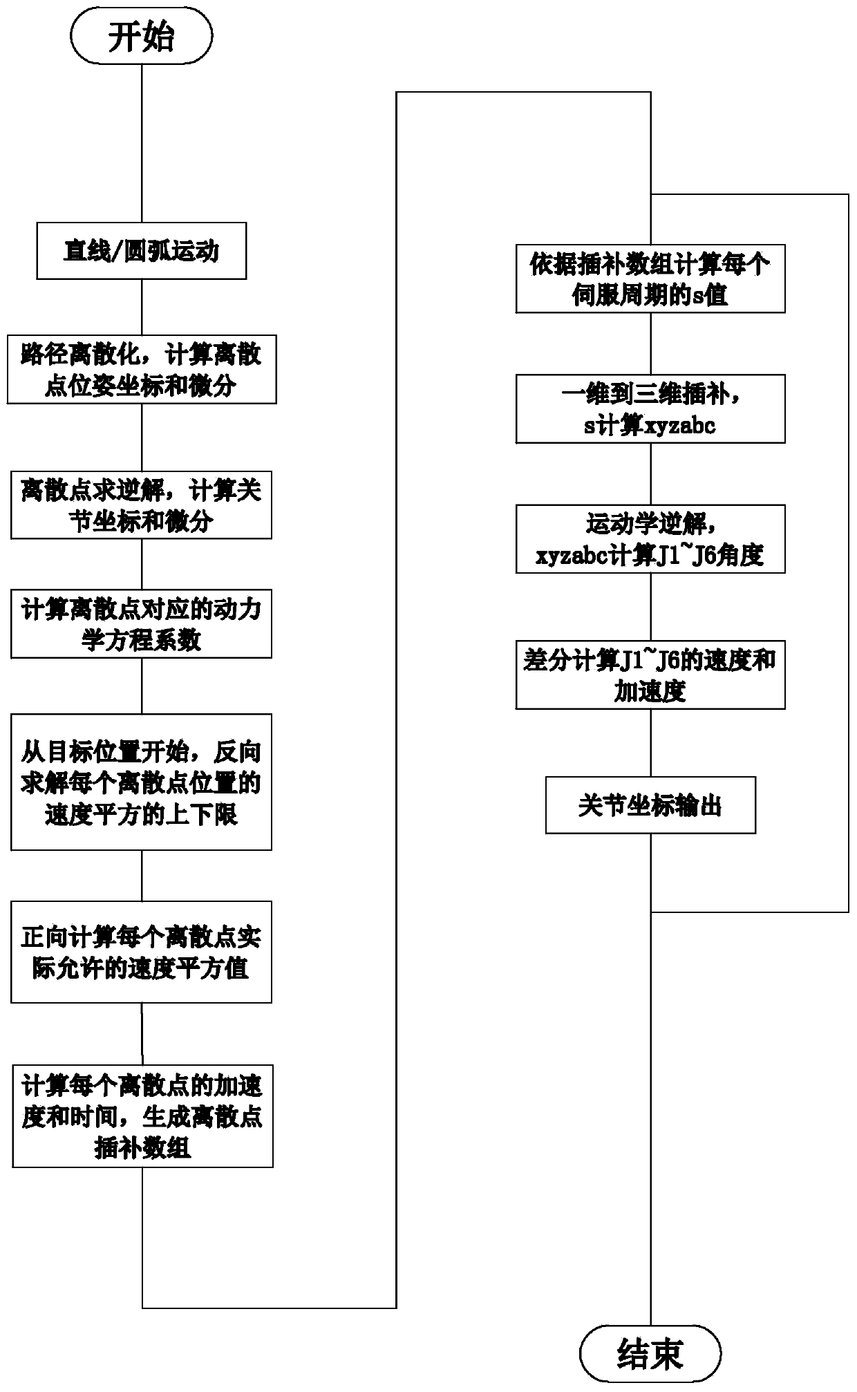
[0059] The robot moves in Cartesian space, and according to the joint space angular velocity, joint space moment, Cartesian space linear velocity and Cartesian space angular velocity are selected as constraints in the motion constraint set, this robot time optimal trajectory planning method includes:

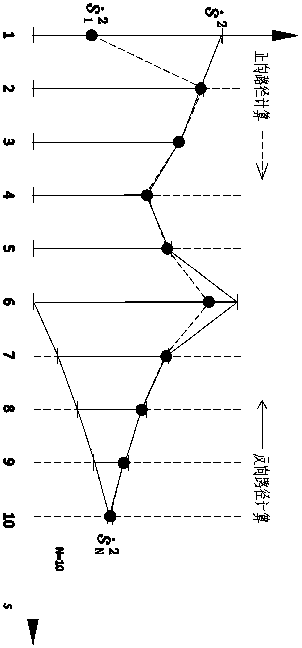
[0060] Create a sequence of discrete point lengths s k : First obtain the task path, calculate the path length s and determine the relationship between the main axis and the slave axis of the robot's position motion and attitude motion, perform equidistant dispersion on the task path, generate several discrete points, and obtain the Cartesian coordinates of the discrete points; where s k =[s 1 ,...s k ...,s N ], k∈[1,2,…,N], k is the discrete point number;

[0061] A. Obtain kinematic parameters: For Cartesian space motion, determine the Cartesian position of the robot. The Cartesian position includes: position information and attitude information based on the coordinate syst...

Embodiment 2

[0172] The difference between this embodiment and the structure and principle of Embodiment 1 is that:

[0173] (1) The motion of the robot is joint space motion. In step A, obtaining joint information, the primary differential s’ is obtained by performing differential calculations on the path length s for each discrete point k with the second differential s" k , for joint space motion, there is no need to solve Cartesian coordinates, and it is not necessary to use kinematics inverse solution for coordinate mapping. according to s k , s' k ,s" k Carry out the calculation of the joint movement displacement q, and the differential calculation of the displacement q with respect to the path length s, and obtain the first differential qs' and the second differential qs", where q is the joint angle, qs' is the joint angular velocity, and qs" is the joint angular acceleration .

[0174] (2) In the motion constraint set, only joint space angular velocity and joint space torque ar...

Embodiment 3

[0176] The structure and principle of this embodiment are basically the same as those of the first embodiment, except that the joint torque in the constraints is replaced by the joint angular acceleration.

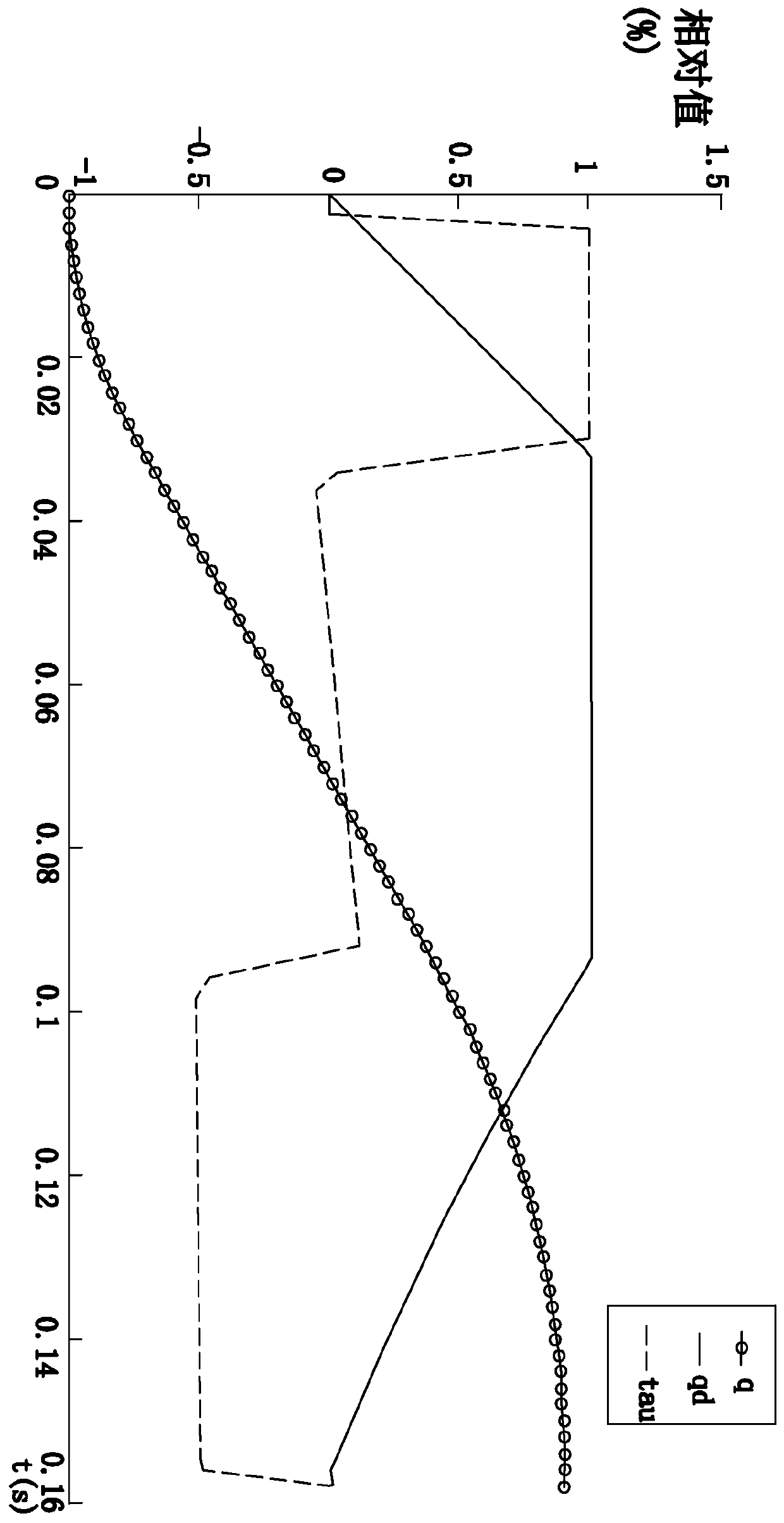
[0177] Suppose the joint angular acceleration of the manipulator in a certain trajectory is And the maximum angular acceleration of the joint is a given value. The minimum angular acceleration is the opposite number of the maximum angular acceleration, and the angular acceleration constraint of the manipulator joint is:

[0178]

[0179] Among them, A j,max is the maximum angular acceleration of the robot joint, A j,min is the minimum angular acceleration of the robot joint.


PUM


Abstract

The invention provides a robot time optimal trajectory planning method, and belongs to the technical field of robot control. The trajectory planning method solves the problem that in the prior art, atrack planning method is poor in practical applicability. The robot time optimal trajectory planning method comprises the steps of obtaining and discretizing a task path and obtaining coordinates of discrete points, and further comprises the steps of A, obtaining kinematics parameters; B, determining variables and constraint conditions, and establishing a constraint inequality; C, calculating to obtain an optimal variable constraint maximum value and an actually allowable optimal solution; D, acquiring information of each discrete point, and generating a discrete point interpolation array; andE, regenerating a discrete point sequence about time, and calculating and outputting joint information about time, so that the adaptability of method application is improved, the calculation difficulty is reduced, and the working efficiency is improved.

Description

technical field [0001] The invention belongs to the technical field of robot control, and relates to a robot time optimal trajectory planning method. Background technique [0002] With the continuous development of industrial automation, the industrial environment is becoming more and more complex, the production demand is fast and changing, and the requirements for the motion performance of industrial robots are getting higher and higher. Robots need to be faster, more accurate and more stable. Therefore, it is necessary to carry out more in-depth planning of the trajectory of the robot. Research. The motion trajectory of traditional robots is mainly S-shaped trajectory, but the S-shaped trajectory adopts fixed motion speed and acceleration, which cannot give full play to the performance of the motor. In order to make the robot move at the maximum speed and shorten the movement time, it is necessary to study the movement of the motor performance under the maximum critical ...

Claims


Application Information

Patent Timeline
Patent Type & Authority Applications(China)
IPC IPC(8): G05D1/02
CPCG05D1/0223G05D1/0214G05D1/0221G05D1/0276
Inventor 赵辉孔民秀徐金龙张海柱张宏伟
Owner ZHEJIANG QIANJIANG ROBOT CO LTD
Why Eureka
Try Eureka