Impact-resistant piezoelectric devices

Inactive Publication Date: 2010-06-17
NIHON DEMPA KOGYO CO LTD
View PDF5 Cites 16 Cited by
  • Summary
  • Abstract
  • Description
  • Claims
  • Application Information

AI Technical Summary

Benefits of technology

[0016]According to the various embodiments as described and claimed herein, the most distal ends of the piezoelectric vibrating piece are protected from breakage or deformation otherwise caused by collisions of the distal ends with the lid plate and/or base plate during physical impacts, particularl

Problems solved by technology

These collisions usually cause fracture or deformation of the piezoelectric vibrating piece and also adversely affect the CI value and/or the oscillation frequency of the piece.
However, these features do not prevent impact-caused collisions of the vibrating arms with the lid 92.
Also, as the piezoelectric device 90 is further miniatu

Method used


Image

  • Impact-resistant piezoelectric devices
  • Impact-resistant piezoelectric devices
  • Impact-resistant piezoelectric devices

Examples


first embodiment

of Piezoelectric Device

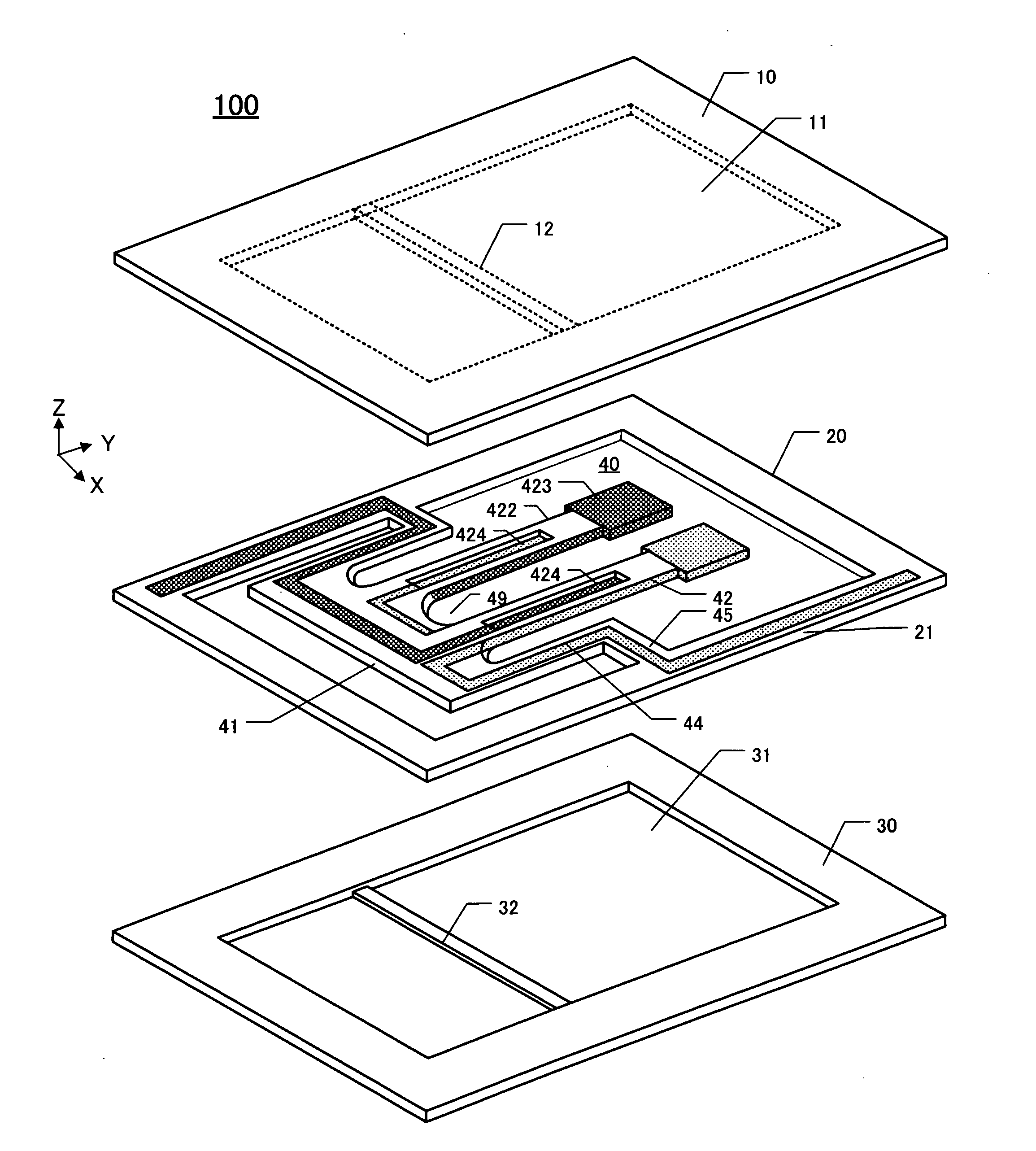
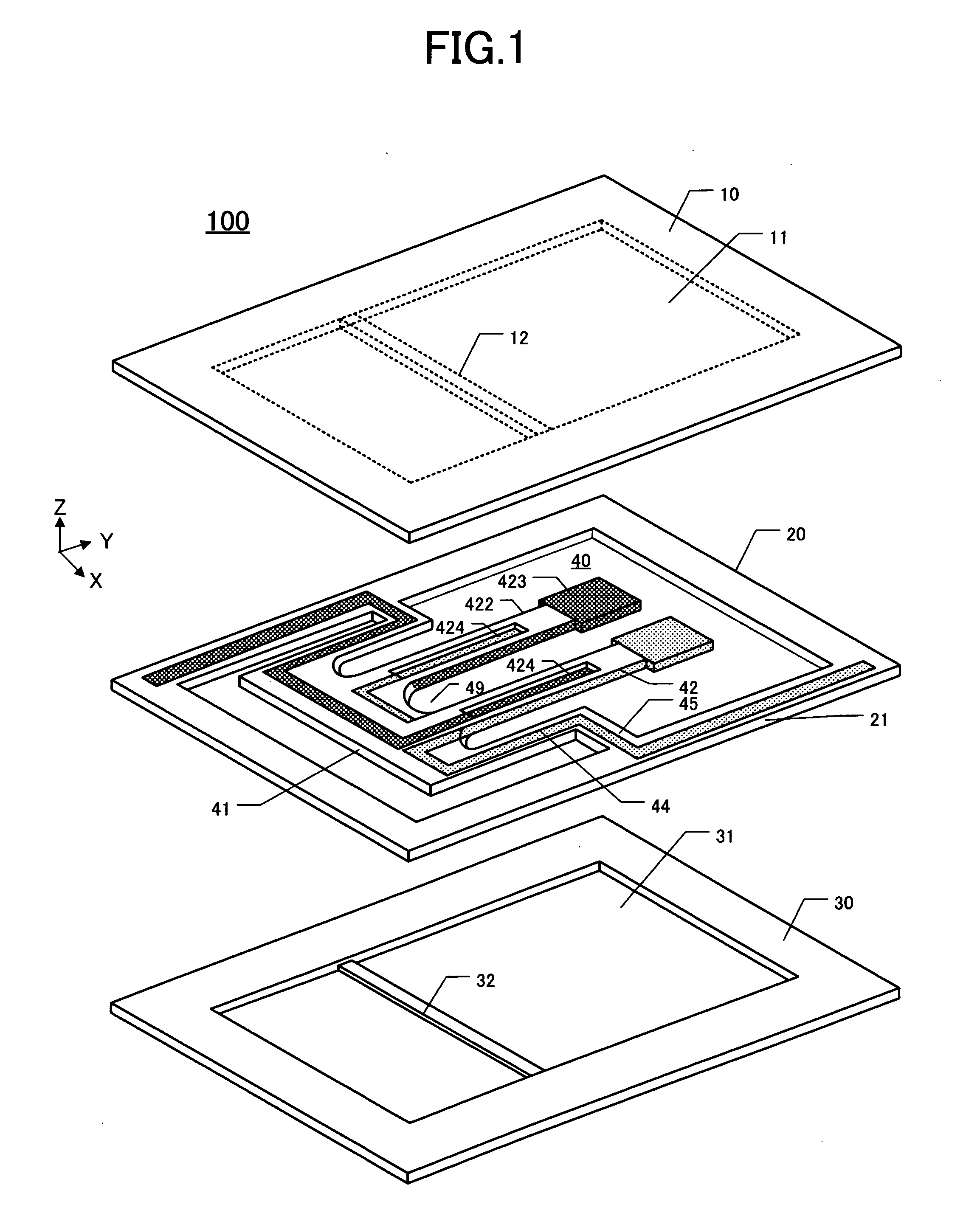
[0028]In this embodiment, the subject piezoelectric device is also termed a piezoelectric “oscillator” or piezoelectric “vibrator.”FIG. 1 is a perspective exploded view of the first embodiment 100. In general, a “piezoelectric device” is a device including a “chip plate” (comprising piezoelectric vibrating “piece” and surrounding “outer frame” made of piezoelectric material), a lid (or “lid plate”), and a package base (or “base plate”). The chip plate is sandwiched between the lid and package base, which are bonded together in the Z-direction to form a packaged device. Bonding of these three plates together can be performed by, for example, siloxane bonding (Si—O—Si) or anodic bonding.

[0029]The package lid 10 comprises a concavity 11 formed by etching into the major surface thereof facing the chip plate 20. The chip plate 20 comprises a piezoelectric vibrating piece 40 situated substantially at the center of the chip plate. The chip plate 20 also includes an o...

second embodiment

of Piezoelectric Device

[0048]In the following discussion of a second embodiment 200 of a piezoelectric device, components thereof that are similar to corresponding components of the first piezoelectric device have the same respective reference numerals and are not described further.

[0049]FIG. 4 is a perspective view of this embodiment, depicting the mutual alignment of the lid plate 10, chip plate 20, and base plate 30. FIG. 5 is a simplified elevational section of the second embodiment, depicting the three plates 10, 20, 30 bonded together. In FIG. 4 the piezoelectric device 200 comprises a lid plate 10 including a concavity 11 on its inner major surface. An arm-movement buffer 13 is located in the concavity 11 at a Y-coordinate that corresponds to the Y-coordinate of the arm portion 422 adjacent the hammer-head portion 423 of the vibrating arms 42. The Y-coordinate of the arm-movement buffer 13 places the buffer at a designated distance from the distal end of the vibrating arms 42...

third embodiment

of Piezoelectric Vibrating Device

[0054]In the following description of the third embodiment 300 of a piezoelectric device, components thereof that are similar to corresponding components of the second and first piezoelectric devices have the same respective reference numerals and are not described further.

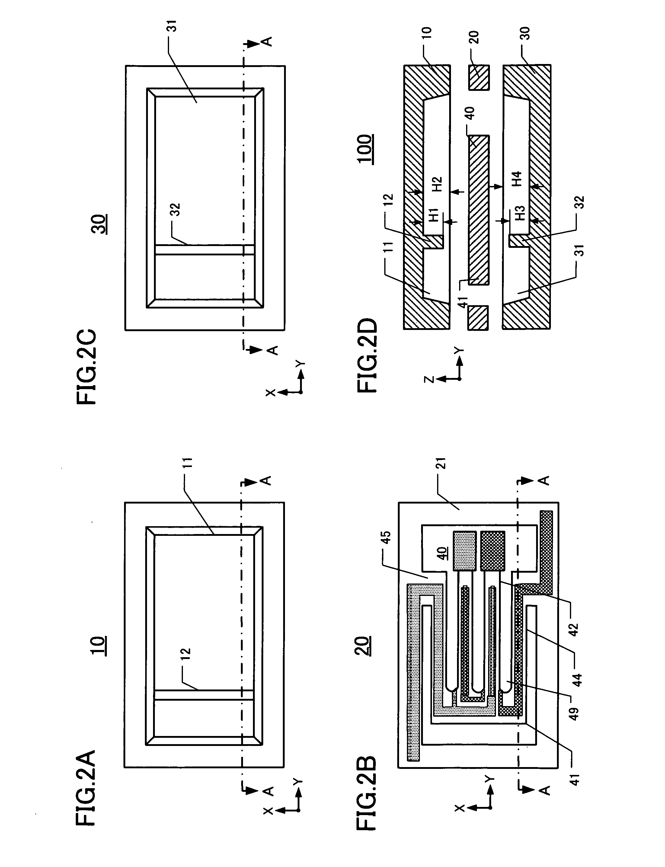
[0055]Reference is made to FIG. 6, which is an enlarged elevational section showing the chip plate 20 sandwiched between the lid plate 10 and base plate 30, which are all bonded together. The figure is accentuated in the vertical direction for increased clarity in showing the various heights discussed below.

[0056]The inner major surface of the lid plate 10 defines a concavity 11 that contains lid base-movement buffers 12 and a lid arm-movement buffer 13. The lid base-movement buffers 12 comprise a first lid base-movement buffer 121 having a Y-coordinate corresponding to the crotch region 40 of the vibrating arms 42. The lid base-movement buffers 12 also comprise a second lid base-m...


PUM


Abstract

Piezoelectric devices are disclosed that include a chip plate sandwiched between a lid plate and a base plate. The chip plate includes a tuning-fork type piezoelectric vibrating piece surrounded by an outer frame. The lid plate includes a concavity on its inner major surface, and the base plate includes a concavity on its inner major surface. The lid plate, chip plate, and base plate are bonded together to form a package containing the piezoelectric vibrating piece. The tuning-fork type piezoelectric vibrating piece includes a base having an X-direction width and at least pair of vibrating arms extending from the base in a Y-direction. The tuning-fork type piezoelectric vibrating piece is coupled to the outer frame by supporting arms extending in the Y-direction outboard of the vibrating arms. The concavity of the lid plate includes at least one base-movement “buffer” extending in the X-direction at a location corresponding to the base of the vibrating piece. The concavity of the base plate includes at least one base-movement buffer extending in the X-direction at a location corresponding to the base.

Description

CROSS-REFERENCE TO RELATED APPLICATION[0001]This application claims priority to and the benefit of Japan Patent Application No. 2008-321000, filed on Dec. 17, 2008, in the Japan Patent Office, the disclosure of which is incorporated herein by reference in its entirety.FIELD[0002]This disclosure pertains to, inter alia, piezoelectric devices having improved impact resistance such as resistance to dropping impact.DESCRIPTION OF THE RELATED ART[0003]In small data devices, such as HDDs (Hard Disc Drives), mobile computers, IC cards, or clock sources for mobile phones, piezoelectric devices are often used. Example piezoelectric devices include piezoelectric vibrating pieces and piezoelectric oscillators. A conventional piezoelectric device as described in U.S. Pat. No. 7,443,086 is shown in elevational section in FIG. 7. The depicted piezoelectric device 90 comprises a piezoelectric vibrating piece 93 mounted on and in a package base 91. The device 90 includes a lid 92 that covers the pi...

Claims


Application Information

Patent Timeline
IPC IPC(8): H01L41/053H01L41/04
CPCH01L41/053H03H9/21H03H9/1035H03H9/0595H10N30/88
Inventor ICHIKAWA, RYOICHI
Owner NIHON DEMPA KOGYO CO LTD
Why Eureka
Try Eureka