Elevator device

A technology of elevators and wind power generation devices, which is applied to elevators in buildings, transportation and packaging, sustainable buildings, etc., and can solve problems such as the active use of hoistway chimney effects, etc.

Inactive Publication Date: 2014-11-12
HITACHI LTD
View PDF8 Cites 8 Cited by
  • Summary
  • Abstract
  • Description
  • Claims
  • Application Information

AI Technical Summary

Problems solved by technology

However, this device does not take into account th

Method used


Image

  • Elevator device
  • Elevator device
  • Elevator device

Examples


no. 1 Embodiment

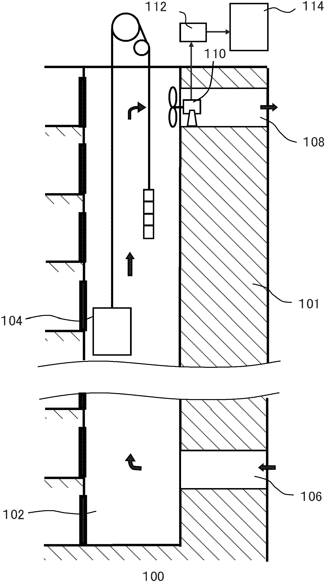
[0018] figure 1 It is a schematic diagram illustrating the elevator apparatus 100 according to the first embodiment of the present invention.

[0019] The elevator device 100 includes a hoistway 102 , a car 104 , a lower connecting road 106 , an upper connecting road 108 , a wind power generator 110 , a storage battery 112 and a control device 114 .

[0020] The hoistway 102 is disposed in the building 101 and provides space for the car 104 to move up and down. The car 104 carries passengers or other loads between different floors by moving up and down in the hoistway 102 .

[0021] The lower floor connection road 106 is arranged on the lower floor side of the shaft 102, and connects the shaft 102 with the outside of the building 101 to form an internal and external air channel at the bottom of the shaft 102. Although figure 1 Only one lower-layer connecting channel 106 is shown in , and multiple lower-layer connecting channels 106 can be provided. The number can be determ...

no. 2 Embodiment

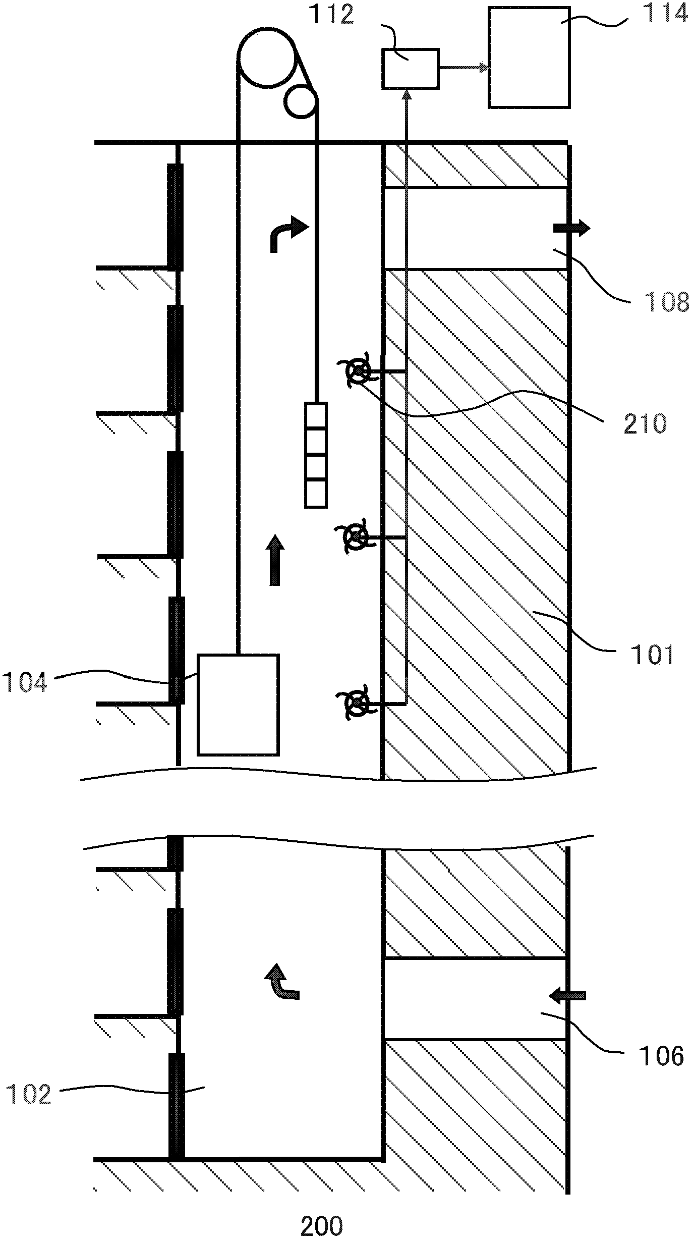
[0040] figure 2 It is a schematic diagram illustrating the elevator apparatus 200 according to the second embodiment of the present invention.

[0041] The elevator device 200 includes a hoistway 102 , a car 104 , a lower connecting road 106 , an upper connecting road 108 , a wind power generator 210 , a storage battery 112 and a control device 114 .

[0042] This embodiment is a modified example of the first embodiment, here figure 1 The wind power generation device 110 in is transformed into a wind power generation device 210 . This embodiment is an example of installing a wind power generator in the hoistway 102 . other components and figure 1 Components marked with the same symbols have the same functions, so descriptions of these components are omitted here.

[0043] Like the wind power generation device 110 , the wind power generation device 210 also refers to a wind power generating set. The wind power generator 210 may be a horizontal-axis wind generator or a ver...

no. 3 Embodiment

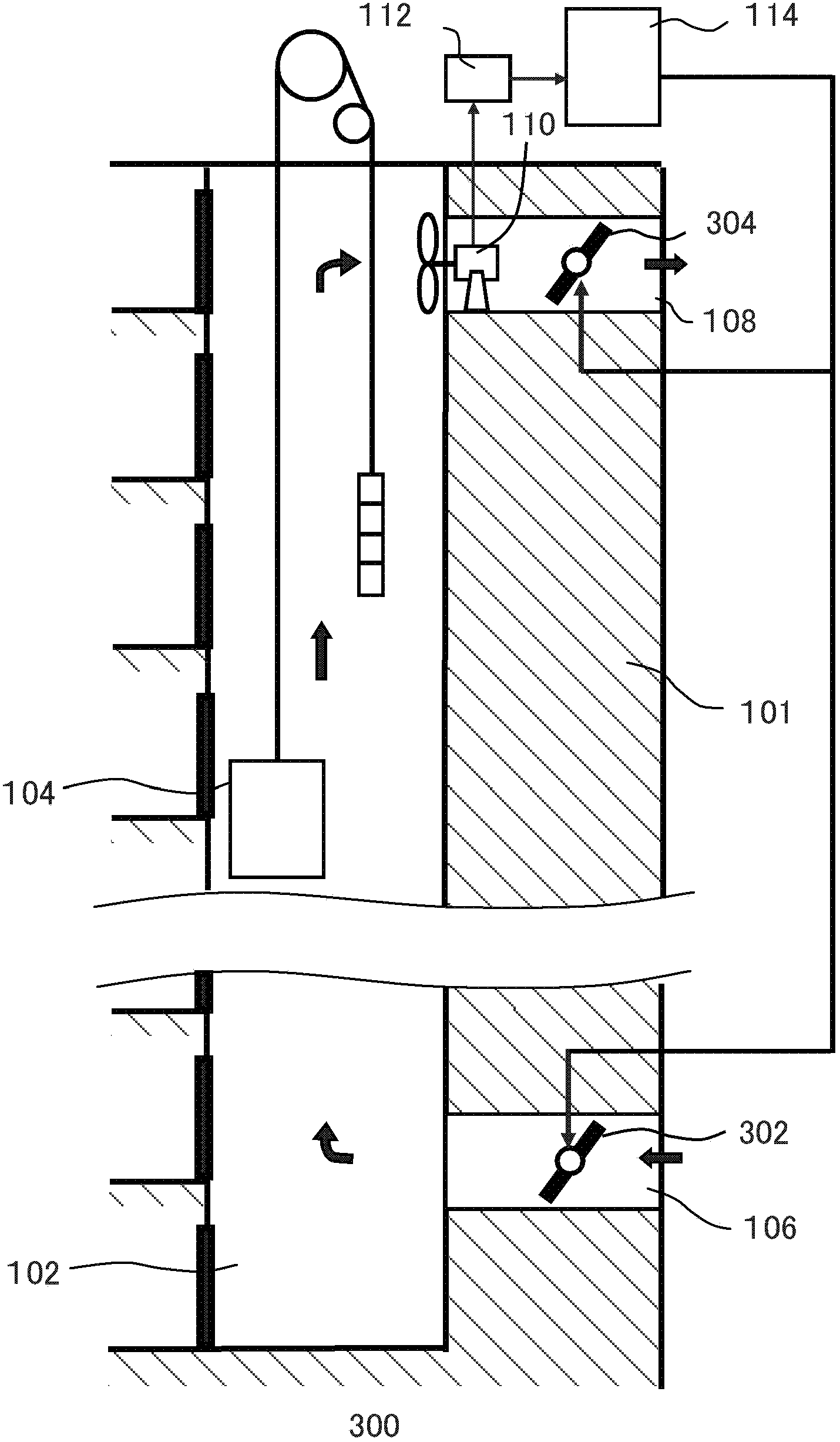
[0046] image 3 It is a schematic diagram illustrating an elevator apparatus 300 according to a third embodiment of the present invention.

[0047] The elevator device 300 includes a shaft 102 , a car 104 , a lower connection 106 , an upper connection 108 , a wind power generator 110 , a storage battery 112 , a control device 114 , a lower electric valve 302 and an upper electric valve 304 .

[0048] This embodiment is a modified example of the first embodiment. This example is in figure 1 In the elevator apparatus 100 of the above-mentioned method, a lower floor electric valve 302 and an upper floor electric valve 304 are added. other components and figure 1 Components marked with the same symbols have the same functions, so descriptions of these components are omitted here.

[0049] The lower electric valve 302 is arranged on the lower connecting channel 106, and under the control of the control device 114, the lower connecting channel 106 can be closed and opened, and t...


PUM


Abstract

The invention relates to an elevator device. The elevator device comprises a hoistway (102) used for rising and falling a car (104) and arranged in a building (101), a control device (114) for controlling the car and related equipment, a lower-layer connecting way (106) arranged at the lower floor side of the hoistway to connect the hoistway with the external of the building, an upper-layer connecting way (108) arranged at the high-floor side of the hoistway to connect the hoistway with the external of the building, a wind power generation device (110) arranged in a space provided with the lower-layer connecting way, the hoistway and the upper-layer connecting way and using an airflow of the space to generate electricity, and an accumulator (112) for storing the electricity generated by the wind power generation device. As the lower-layer connecting way and the upper-layer connecting way are arranged, the airflow is kept passing through among the lower-layer connecting way, the hoistway and the upper-layer connecting way. The wind power generation device can use the airflow to continuously generate the electricity at ordinary times or even in the power failure time so as to deal with the abnormal condition of long-time power failure.

Description

technical field [0001] The present invention relates to an elevator device, which includes a hoistway provided in a building for the up and down movement of a car; and a control device for controlling the car and its related equipment. Background technique [0002] In order to cope with the emergency situation that the common power supply that the building provides to the elevator takes place, the elevator device is often provided with a backup power supply. Japanese Patent Publication No. 2-198994 discloses an elevator automatic implantation device using a storage battery as a backup power source. However, the duration of battery life is limited. Japanese Patent Laid-Open No. 6-263342 discloses an elevator control running device using a small generator as a backup power source. However, this small generator is not only expensive, but also requires prime movers such as diesel engines to drive, consumes fuels such as diesel, and causes air pollution. [0003] In addition, ...

Claims


Application Information

Patent Timeline
IPC IPC(8): B66B9/00
CPCY02B50/00
Inventor 加藤可奈子大沼直人
Owner HITACHI LTD
Why Eureka
Try Eureka