Wind deflector and vehicle installed with the wind deflector

An air guide hood and mounting hole technology is applied in the field of the air guide hood and the vehicle on which the air guide hood is installed, which can solve the problems of poor heat dissipation effect and difficult heat dissipation airflow of the vehicle energy system, and achieves the improvement of the heat dissipation effect and the installation efficiency. Effect

Active Publication Date: 2019-08-09
ZHENGZHOU YUTONG BUS CO LTD
View PDF11 Cites 0 Cited by
  • Summary
  • Abstract
  • Description
  • Claims
  • Application Information

AI Technical Summary

Problems solved by technology

[0004] The purpose of the present invention is to provide a wind guide cover to solve the problem that when the installation position of the vehicle-mounted energy system is close to the partition surface of the hyperbaric cabin and the flexible soft conduit cannot be used, it is difficult for the heat dissipation airflow to form a directional air duct to pass into the vehicle-mounted energy system box. It leads to the problem of poor heat dissipation effect of the vehicle-mounted energy system; meanwhile, the purpose of the present invention is also to provide a vehicle with the above-mentioned wind deflector installed

Method used


Image

  • Wind deflector and vehicle installed with the wind deflector
  • Wind deflector and vehicle installed with the wind deflector
  • Wind deflector and vehicle installed with the wind deflector

Examples


Embodiment Construction

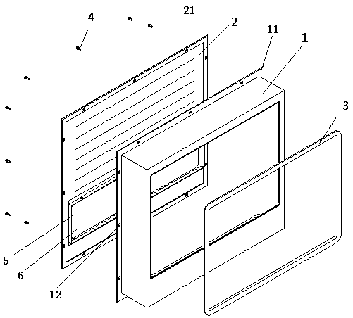
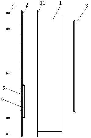
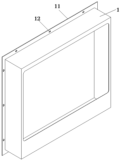
[0027] Embodiments of the present invention will be further described below in conjunction with the accompanying drawings.

[0028] A specific embodiment of a wind guide cover of the present invention, such as Figure 1 to Figure 6 As shown, the shown air guide cover includes an air guide cavity body 1 extending in the front and rear direction, and the front end of the air guide cavity cavity 1 is provided with a hole for close contact with the partition surface for airflow to enter the inside of the air guide cavity cavity. The front-end inlet and the rear-end outlet are used to be close to the air inlet surface of the vehicle energy system box 9 . In this embodiment, the rear end outlet of the air guide cavity body 1 is rectangular and is consistent with the size of the air inlet surface of the vehicle energy system box 9. In order to prevent the heat dissipation air flow delivered by the air guide cavity cavity 1 from The gap between the opening of the rear end of the body...


PUM


Abstract

The invention relates to a wind scooper and a vehicle with the same. The wind scooper comprises a wind guiding cavity body extending in the front-back direction. A front end inlet for being tightly attached to a separation face to enable airflow to enter the wind guiding cavity body and a rear end outlet for being tightly attached to the wind inlet face of a vehicle-mounted energy box are formed in the wind guiding cavity body. An installation structure for installing a vehicle frame is further arranged on the wind guiding cavity body. The wind guiding cavity body occupies the space between the vehicle-mounted energy system box and the separation face of a hyperbaric cabin. Cooling airflow enters the wind guiding cavity body from the separation face and then is led into the vehicle-mounted energy system box along a directional air flue formed by the wind guiding cavity body, the amount of airflow led into the vehicle-mounted energy system box is ensured, and the cooling effect of the vehicle-mounted energy system is improved, so that the problems that the cooling effect of the vehicle-mounted energy system is poor in effect due to the fact that the distance between the installation position of the vehicle-mounted energy system and the separation face of the hyperbaric cabin is small, a flexible soft catheter cannot be used, and cooling airflow cannot be led into the vehicle-mounted energy system box through the directional air flue which is hard to form are solved.

Description

technical field [0001] The invention relates to a wind guide cover and a vehicle on which the wind guide cover is installed. Background technique [0002] The depletion of traditional energy and the pollution and damage to the air environment have made energy reform a global "green" new deal. While promoting this green revolution, pure electric and hybrid vehicles have also become the focus of the country's new energy industrialization . The on-board energy system is one of the main systems of new energy vehicles, and its performance determines the performance of the vehicle. At present, the power lithium battery is the mainstream form of vehicle energy. In order to improve the service life of the battery, it is necessary to conduct sufficient thermal management on the battery system. Through a reasonable air duct structure, the battery has good ventilation and heat dissipation effects and provides a good temperature environment. sex. [0003] The installation position of...

Claims


Application Information

Patent Timeline
Patent Type & Authority Patents(China)
IPC IPC(8): B60K11/06B60K11/08H01M10/613H01M10/625H01M10/6561
CPCB60K11/06B60K11/08H01M10/613H01M10/625H01M10/6561H01M2220/20Y02E60/10
Inventor 李小尹周时国陈凯董成坤王坤朱建锦
Owner ZHENGZHOU YUTONG BUS CO LTD
Why Eureka
Try Eureka