Air conditioner defrosting control method and air conditioner system

A control method and technology for an air conditioner, which are applied in the defrosting control of air conditioners and in the field of air conditioner systems, can solve the problems of long defrosting time, large fluctuations in indoor temperature, affecting indoor heating effect, etc. The effect of avoiding large fluctuations in indoor temperature and shortening the defrosting time

Active Publication Date: 2013-12-25
GD MIDEA AIR-CONDITIONING EQUIP CO LTD
View PDF7 Cites 18 Cited by
  • Summary
  • Abstract
  • Description
  • Claims
  • Application Information

AI Technical Summary

Problems solved by technology

When the outdoor temperature is low, the temperature of the outdoor heat exchanger 3 is usually lower than 0 degrees. After a period of operation, the outdoor heat exchanger 3 will frost, and the temperature of the outdoor heat exchanger 3 will become lower and lower after frosting. Seriously affect the indoor heating effect
Therefore, it is necessary to defrost the outdoor heat exchanger 3 after a period of time, and the traditional defrosting mode is to reverse the direction of the four-way valve 2, that is, the four-way valve 2 changes from a→d in the original heating cycle. The b→c connection is switched to the refrigeration cycle a→b, d→c connection. At the same time, the bypass valve 6 is opened so that the refrigerant discharged from the exhaust port A1 of the indoor heat exchanger 5 also directly enters the outdoor heat exchanger through the bypass valve 6. 3 To achieve bypass defrosting of the air conditioner, the indoor heat exchanger 5 will always absorb the heat inside the room during the whole defrosting process, and the compressor 1 needs to be shut down twice from the beginning to the end, repeated defrosting will not only cause fluctuations in the indoor temperature Larger and longer defrosting time

Method used


Image

  • Air conditioner defrosting control method and air conditioner system
  • Air conditioner defrosting control method and air conditioner system
  • Air conditioner defrosting control method and air conditioner system

Examples


Embodiment Construction

[0051] The technical solutions of the present invention will be further described below in conjunction with the accompanying drawings and specific embodiments. It should be understood that the specific embodiments described here are only used to explain the present invention, not to limit the present invention.
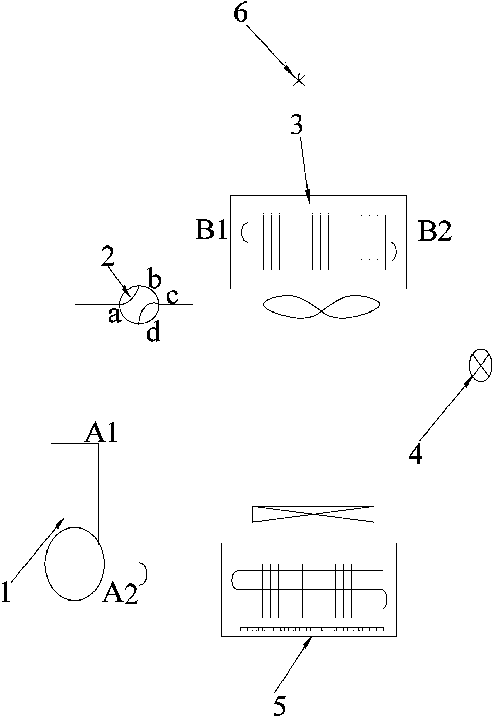
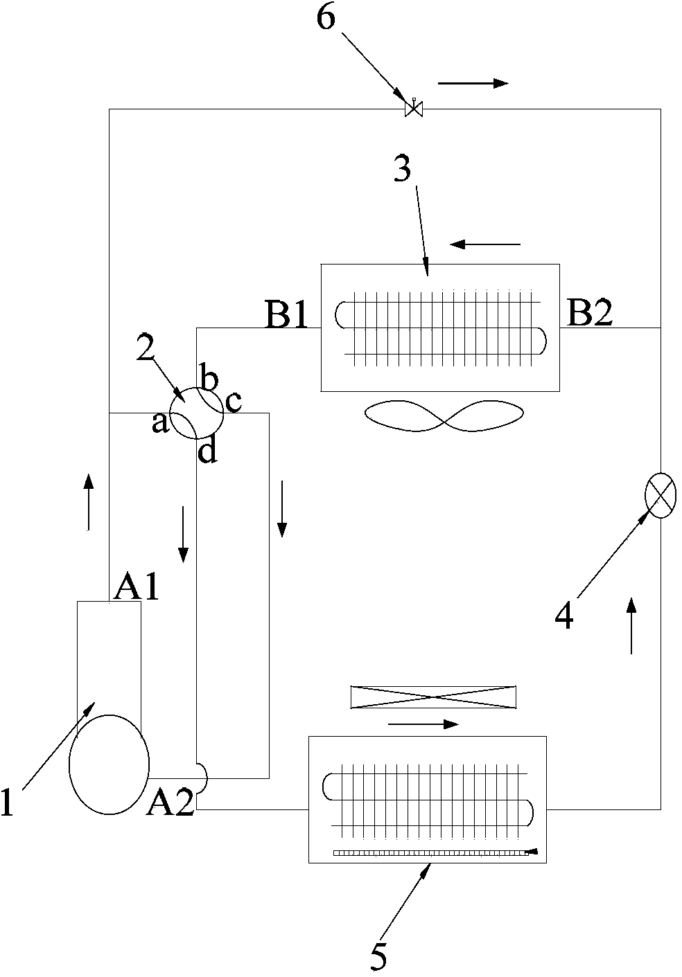
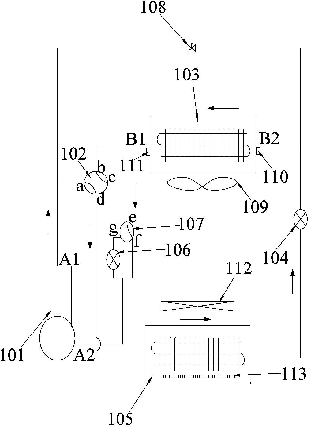
[0052] The main idea of ​​the present invention is to set two kinds of defrosting flow paths, and during the operation of the air conditioner, detect the operating parameters of the air conditioner, and select when to enter the defrosting flow path according to the operating parameters, When to quit defrosting. The invention can not only overcome the big fluctuation of indoor temperature during the defrosting of the existing air conditioning system, but also greatly shorten the defrosting time.

[0053] Specifically, such as image 3 and Figure 4 As shown, the embodiment of the present invention provides a first embodiment of an air conditioner system. The air cond...


PUM


Abstract

The invention discloses an air conditioner system comprising a compressor, a four-way valve, an outdoor heat exchanger, a first throttling part, an indoor heat exchanger, a first switch block, a three-way valve, a second throttling part and a control device. The first switch block is connected between an exhaust port of the compressor and an inlet of the outdoor heat exchanger during heating; the three-way valve is connected between the four-way valve and an air return port of the compressor; the second throttling part is connected between a port of the three-way valve and the air return port of the compressor. The control device firstly controls the first switch block to be turned on to perform bypass defrosting on the air conditioner when defrosting is needed, and controls the three-way valve to reverse so as to enable the second throttling valve to prolong staying time of refrigerant in the outdoor heat exchanger when bypass defrosting is not clean. The invention further discloses a defrosting control method of the air conditioner system. By the system and the method, defrosting time is shortened, and large indoor temperature fluctuation caused by reversing and defrosting of the four-way valve in the prior art is avoided.

Description

technical field [0001] The invention relates to the field of air conditioners, in particular to an air conditioner defrosting control method and an air conditioner system. Background technique [0002] Such as figure 1 and figure 2 As shown, the current traditional air conditioning system consists of a compressor 1, a four-way valve 2, an outdoor heat exchanger 3, a throttling component 4, and an indoor heat exchanger 5. The compressor 1 drives the refrigerant to circulate in the system. When the refrigerant flows When passing through compressor 1, four-way valve 2a→four-way valve 2b→outdoor heat exchanger 3→throttling component 4→indoor heat exchanger 5→four-way valve 2d→four-way valve 2c→compressor 1, the formed It is the refrigeration cycle that lowers the temperature in the room. When the refrigerant flows through compressor 1→four-way valve 2a→four-way valve 2d→indoor heat exchanger 5→throttling component 4→outdoor heat exchanger 3→four-way valve 2b→four-way valve 2...

Claims


Application Information

Patent Timeline
Patent Type & Authority Applications(China)
IPC IPC(8): F24F11/00F24F11/02
Inventor 黎辉玲周向阳
Owner GD MIDEA AIR-CONDITIONING EQUIP CO LTD
Why Eureka
Try Eureka