Connected box-shaped laminating heat exchanger

A heat exchanger and combined box technology, which is applied in the field of combined box-shaped stacked heat exchangers, can solve the problems of inability to resist the impact of refrigerant working pressure, limited pressure bearing capacity of aluminum heat exchange plates, etc.

Active Publication Date: 2013-12-25
缪志先
View PDF8 Cites 6 Cited by
  • Summary
  • Abstract
  • Description
  • Claims
  • Application Information

AI Technical Summary

Problems solved by technology

[0003] The disadvantage of the above-mentioned box-shaped stacked heat exchanger is that when this type of box-shaped stacked heat exchanger is made of a material like aluminum, it is used in a compressed air freeze dryer, and the compressed air preheating section and the When the compressed air refrigerant refrigeration section is connected together, due to the limited pressure bearing capacity of the aluminum heat exchange plate, at the end of the refrigerant channel, only the thickness of the aluminum plate at the corner hole of the aluminum heat exchange plate cannot resist the work of the refrigerant. The impact of pressure cannot effectively make the corner hole of the heat exchanger and the entire heat exchanger have sufficient anti-burst pressure and anti-fatigue capabilities

Method used


Image

  • Connected box-shaped laminating heat exchanger
  • Connected box-shaped laminating heat exchanger
  • Connected box-shaped laminating heat exchanger

Examples


Embodiment Construction

[0027] Further description will be made below in conjunction with embodiments and illustrations.

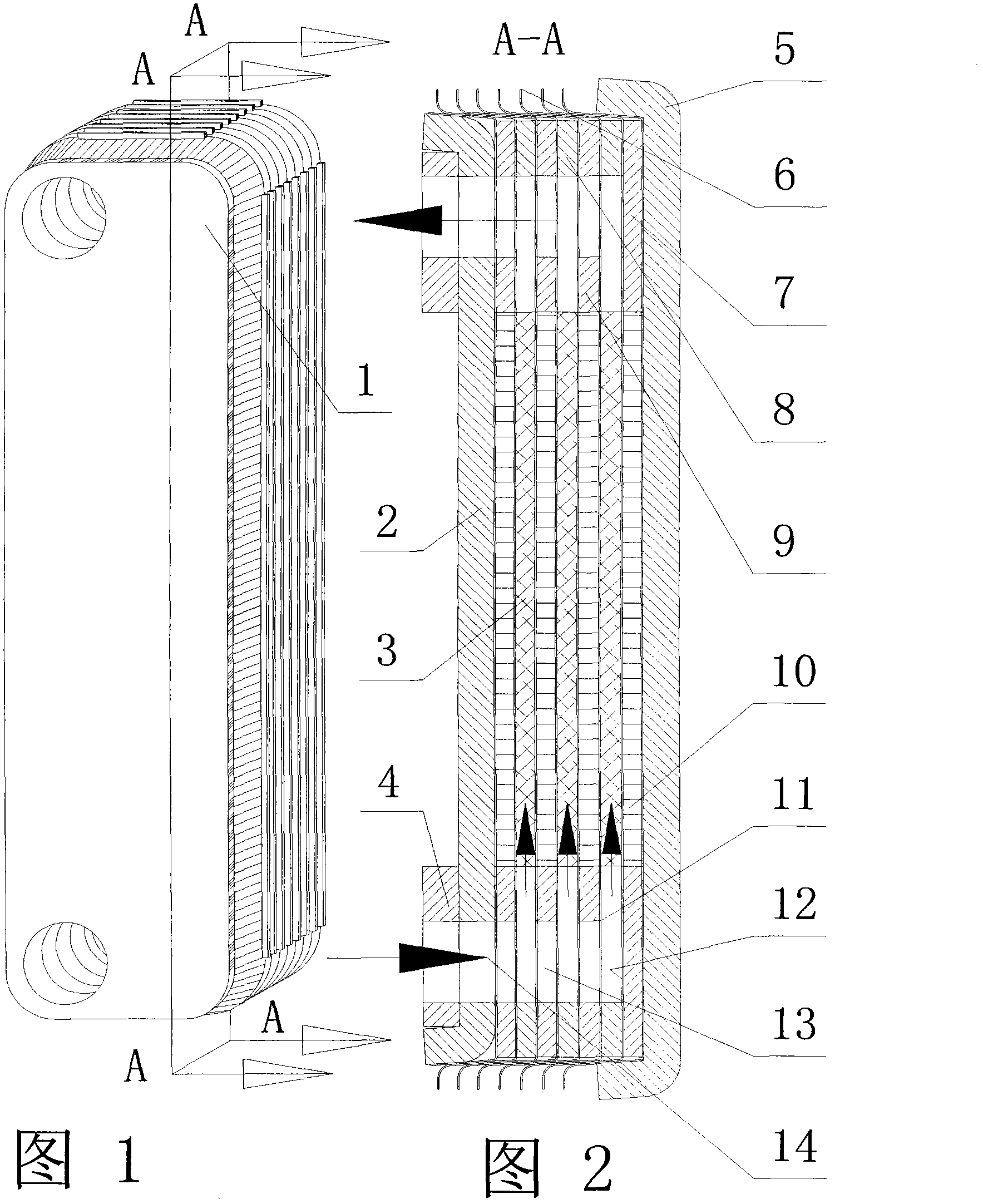
[0028] figure 1 The 1 in the figure represents a single box-shaped laminated heat exchanger. The heat exchange medium inside the heat exchanger adopts the heat exchange mode of the same side flow. It can be seen from the surface of the three-dimensional heat exchanger that the left side of the front baffle There are two through holes and pipes on the upper and lower sides. This pipe can be considered as a through hole and pipe through which a certain heat exchange medium enters and exits the heat exchanger, and another kind of heat exchange that is opposite to it. The circulation duct of the medium Y is behind the front baffle, and there is no corresponding through hole on the front baffle. For this reason, the section A-A is set up to illustrate the pipeline behind the front baffle.

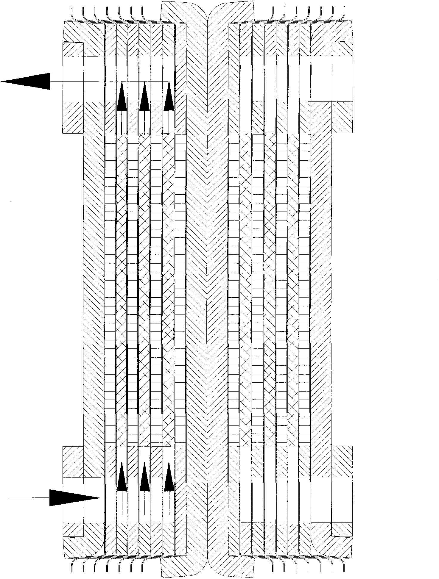
[0029] figure 2 expressed figure 1 The A-A section of , where 2 represents the rear baffle,...


PUM


Abstract

The invention discloses a connected box-shaped laminating heat exchanger. Each single box-shaped laminating heat exchanger consists of a plurality of heat exchange plate fins which are in the shape of an inclined edge box and can be laminated together, wherein angular holes through which a heat exchange medium can flow and heat exchange devices which can perform inter-wall heat exchange are arranged in each single box-shaped laminating heat exchanger; the angular holes in the heat exchangers are distributed in the two ends of each heat exchange plate fin; the heat exchange devices are positioned on the middle parts of the heat exchange plate fins; a front baffle plate, a rear baffle plate and a rear reinforcing plate which are hermetically linked with each single box-shaped laminating heat exchanger are arranged on the single box-shaped laminating heat exchanger; the materials of the front baffle plate, the rear baffle plate and the rear reinforcing plate are much thicker than the material of the heat exchange plate fins. The connected box-shaped laminating heat exchanger is characterized in that the single box-shaped laminating heat exchangers with the front baffle plates, the rear baffle plates and the rear reinforcing plates are hermetically linked together, and a linked wall plate with enough thickness is formed at the end of a heat exchange medium passage in a hermetical linkage form.

Description

technical field [0001] The invention relates to a heat exchanger, in particular to a conjoined box-shaped laminated heat exchanger. Background technique [0002] A box-shaped stacked heat exchanger refers to a plurality of heat exchange plates with sloped edges stacked in sequence, and the slopes on the edges of each heat exchange plate are sealed and connected together. There is a heat exchange medium inside the box-shaped stacked heat exchanger. The corner holes for circulation and the heat exchange device for heat exchange in the partition wall, the corner holes in the heat exchanger are distributed at both ends of each heat exchange plate, and the heat exchange device is located in the middle of the heat exchange plate. [0003] The disadvantage of the above-mentioned box-shaped stacked heat exchanger is that when this type of box-shaped stacked heat exchanger is made of a material like aluminum, it is used in a compressed air freeze dryer, and the compressed air preheat...

Claims


Application Information

Patent Timeline
Patent Type & Authority Applications(China)
IPC IPC(8): F28D9/00F28F3/10
Inventor 缪志先
Owner 缪志先
Why Eureka
Try Eureka