
A heat exchange system of heat recovery exchanger

A heat exchange system and switch technology, applied in the field of heat exchange systems, can solve the problems of waste of energy resources, low heat exchange efficiency, low heat utilization rate, etc., and achieve the effects of avoiding hazards, meeting heat transfer requirements, and high safety.

Active Publication Date: 2020-09-04
广德美好包装科技股份有限公司
View PDF10 Cites 0 Cited by
  • Summary
  • Abstract
  • Description
  • Claims
  • Application Information

AI Technical Summary

Problems solved by technology

[0003] The general heat exchange system is similar to the traditional heat exchanger, the heat exchange efficiency is low, and the heat transfer is one-time. It is equipped with a circular heat transfer structure, which causes most of the heat in the thermal fluid passing through the heat exchanger to be lost as waste heat; The exported heat after heat exchange inside the heat exchanger is not provided with a circulation heat recovery structure between the heat exchanger, resulting in poor heat transfer effect and low heat utilization rate in general heat exchange systems, resulting in a large waste of energy resources

Method used


Image

  • A heat exchange system of heat recovery exchanger
  • A heat exchange system of heat recovery exchanger
  • A heat exchange system of heat recovery exchanger

Examples


Embodiment 1

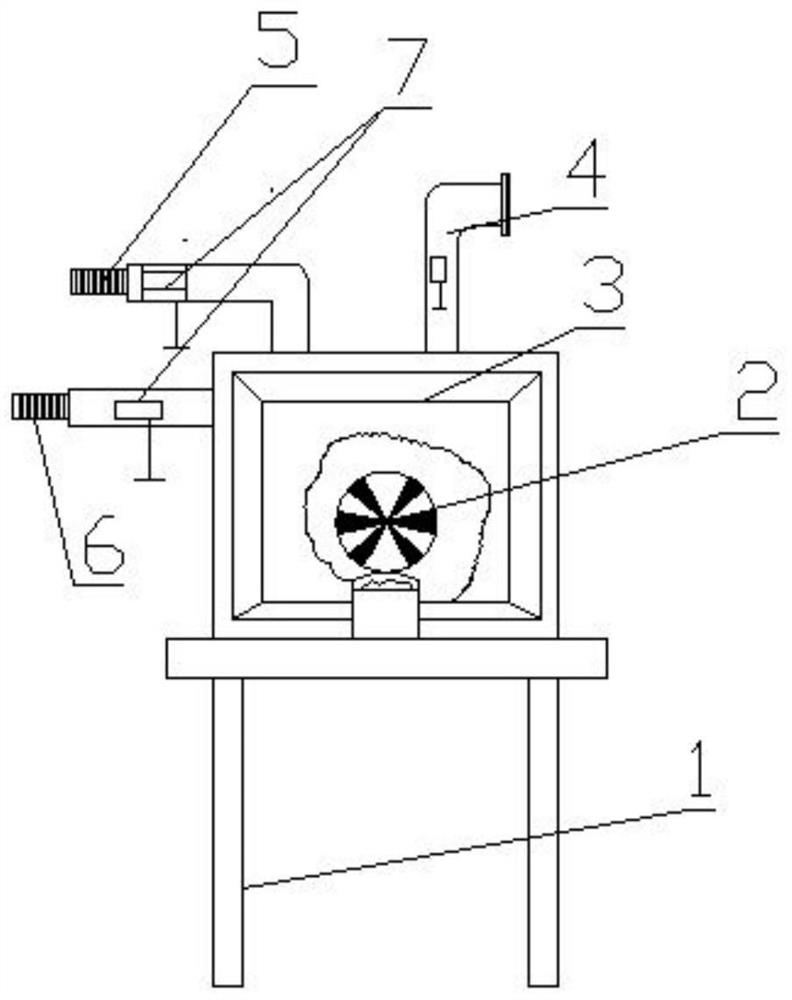
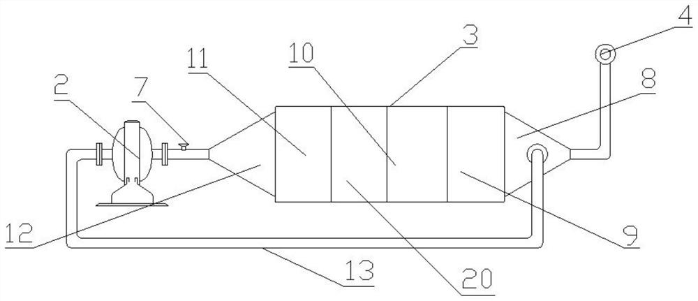
[0025] Such as Figure 1-7 As shown, the technical solution adopted by the present invention is: a heat exchange system of a heat recovery exchanger, the main structure of the heat exchange system is set as a heat exchanger 3, and one end of the heat exchanger 3 is connected to a heat circulation fan 2 A heat exchange tube 16 is installed inside the heat exchanger 3 , and a flow turbulence corrugation 19 is arranged inside the heat exchange tube 16 .

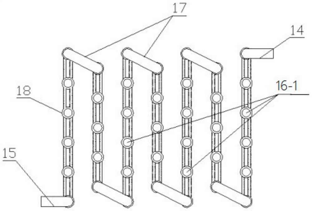
[0026] The front end of the heat exchanger 3 is set as a filter area 8, and the downstream of the filter area 8 is set as a planar heat exchange area 9, and the planar heat exchange area 9 is equipped with serpentine heat exchange tubes 16-1 arranged in a plane. The downstream of the planar heat exchange area 9 is set as a spiral heat exchange area 10, and the inside of the spiral heat exchange area 10 is equipped with spiral heat exchange tubes 16-2 arranged one-sidedly. In the exchange area 20, irregular heat exchange tubes 1...

Embodiment 2

[0035] The difference between this embodiment and embodiment 1 is:

[0036] The inside of the filter area 8 is filled with a mixture of activated carbon and alkaline reagent, the mixing ratio is 5:1, wherein the alkaline reagent is a mixture of wet sodium bicarbonate and sodium hydroxide, and the mixing ratio is 3:1.

Embodiment 3

[0038] The difference between this embodiment and embodiment 1 is:

[0039] The inside of the filter area 8 is filled with a mixture of activated carbon and an alkaline reagent, and the mixing ratio is 3:1, wherein the alkaline reagent is a mixture of wet sodium bicarbonate and sodium hydroxide, and the mixing ratio is 2:1.


PUM


Abstract

The invention relates to a heat exchange system of a heat recovery exchanger, and aims to provide the heat exchange system with good heat exchange effect, high heat transfer temperature difference andcircular heat returning. A main structure of the heat exchange system is arranged as a heat exchanger; one end of the heat exchanger is connected with a heat circulating fan; a filter area is arranged at the front end of the heat exchanger; the downstream of the filter area is arranged as a plane heat exchange area; the downstream of the plane heat exchange area is arranged as a spiral heat exchange area; the downstream of the spiral heat exchange area is arranged as a disordered heat exchange area; the downstream of the disordered heat exchange area is arranged as a horn heat exchange area;and the downstream of the horn heat exchange area is arranged as a hot air flow separation area. Multiple heat exchange tubes are arranged in the heat exchange system, and ripples are arranged in theheat exchange tubes, so that the heat transfer and mass transfer disturbance is increased, the heat transfer and the mass transfer are facilitated, and the heat exchange efficiency is improved; fluidscircularly transfer heat in the heat exchanger by multiple times, so that the heat transfer temperature difference is increased, and the heat transfer requirements are met; and the system adopts semi-automatic operation, and is flexible in control, simple and practical.

Description

technical field [0001] The invention relates to the technical field of heat recovery and exchange, in particular to a heat exchange system of a heat recovery exchanger. Background technique [0002] The air compressor heat recovery device has been widely used in industrial and mining enterprises and daily life needs, and the effect of energy saving and emission reduction is obvious. However, the heat recovery devices on the market are not perfect, and the potential for energy saving can be further tapped. For example, the existing heat recovery switches are all installed in a split type. The main defect of this structure is that the distance between the heat exchanger and the heat demand device is long, which will inevitably lead to loss of heat energy and waste of materials, and fail to achieve energy saving. The best effect of emission reduction; in addition, the long distance between the heat exchanger and the heat demand device causes the pipeline to be messy, and the o...

Claims


Application Information

Patent Timeline
Patent Type & Authority Patents(China)
IPC IPC(8): F26B21/00
CPCF26B21/002F26B21/003Y02P70/10
Inventor 林元针
Owner 广德美好包装科技股份有限公司
Learn More