Anti-siphon structure in oil suction inlet of lubricating oil pump

A lubricating oil pump and anti-siphon technology, applied in the direction of engine lubrication, turbine/propulsion lubrication, engine components, etc., can solve problems such as increasing the resistance of the lubricating oil system

Active Publication Date: 2014-01-01
AECC SHENYANG ENGINE RES INST
View PDF7 Cites 3 Cited by
  • Summary
  • Abstract
  • Description
  • Claims
  • Application Information

AI Technical Summary

Problems solved by technology

[0003] There are two main methods of anti-siphon design that are widely used at present. One is to realize anti-siphon through the one-way valve on the lubricating oil booster pipeline, and to block the flow path where siphon occur

Method used


Image

  • Anti-siphon structure in oil suction inlet of lubricating oil pump
  • Anti-siphon structure in oil suction inlet of lubricating oil pump
  • Anti-siphon structure in oil suction inlet of lubricating oil pump

Examples


Embodiment 1

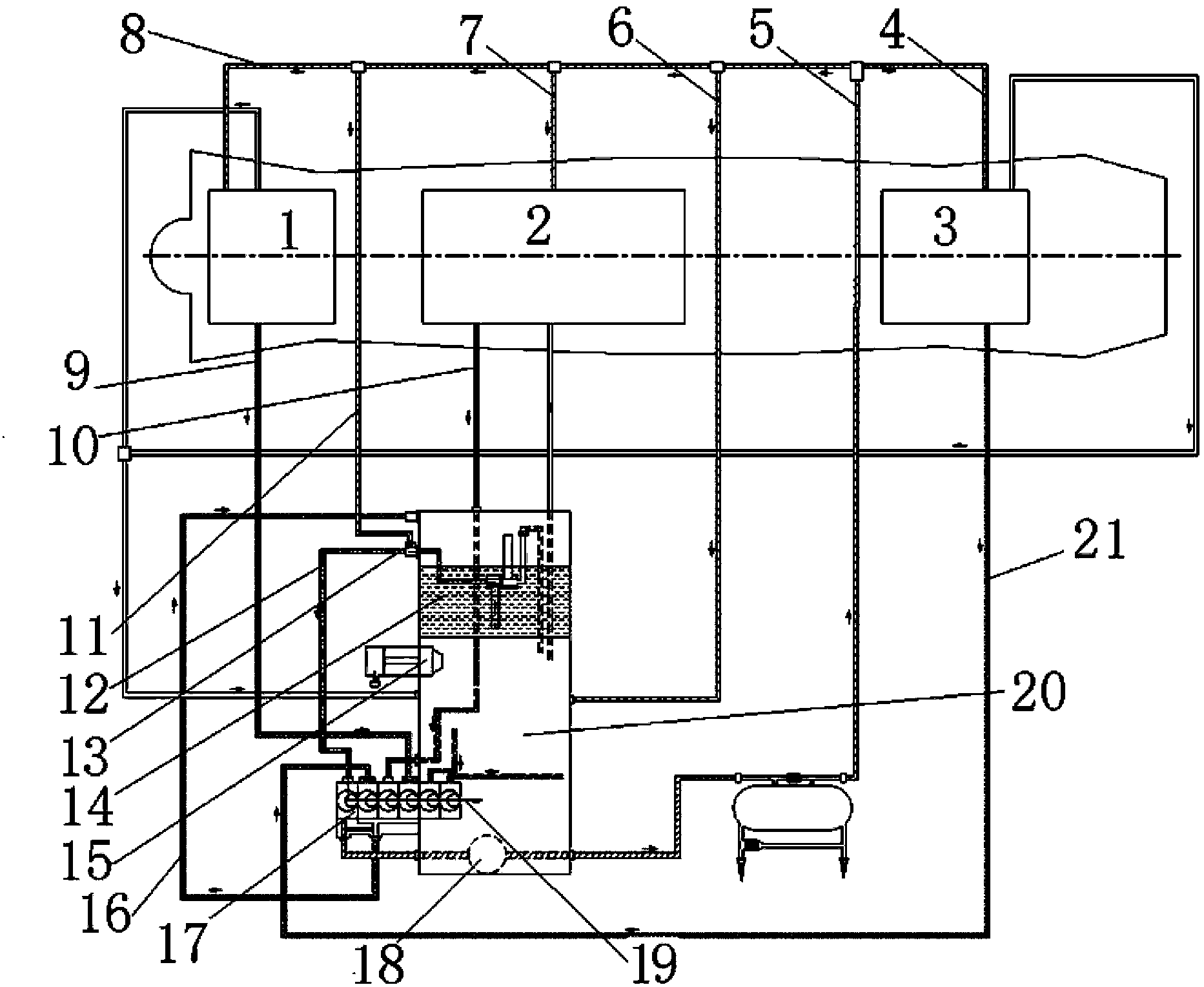
[0017] The invention provides an anti-siphon structure at the oil suction inlet of the lubricating oil pump, which is characterized in that: the anti-siphon structure at the oil suction inlet of the lubricating oil pump is specifically that the nozzles in the bearing cavities of the engine are higher than the liquid level of the fuel tank by 1 ~1.5m, while the nozzle in the accessory casing is 50-200mm lower than the liquid level of the lubricating oil tank; an anti-siphon pipeline is led from the oil suction inlet of the lubricating oil pump to the lubricating oil supply road of the front bearing cavity, and the anti-siphon pipeline is set on the liquid level of the lubricating oil tank Above, to prevent the siphon phenomenon after the engine stops, when the siphon phenomenon occurs, along with the flow of lubricating oil in the oil suction inlet pipe from the lubricating oil tank to the lubricating oil pump, the air inside the bearing cavity is introduced into this pipeline, t...


PUM

PropertyMeasurementUnit
Diameteraaaaaaaaaa

Abstract

The invention relates to an anti-siphon structure in an oil suction inlet of a lubricating oil pump. A nozzle inside each bearing cavity of an engine is 1m to 1.5m higher than the liquid surface of an oil tank, and a nozzle inside an accessory case is 50mm to 200mm lower than the liquid surface of the lubricating oil tank; an anti-siphon pipeline is guided out from the oil suction inlet of the lubricating oil pump onto a lubricating oil supply oil circuit of the front bearing cavity, the anti-siphon pipeline is arranged above the liquid surface of the lubricating oil tank, a throttling nozzle is arranged in an outlet of an anti-siphon pipeline at the oil suction inlet of the lubricating oil pump, so that the air clogging phenomenon of the lubricating oil pump caused by excessive suction of air in the starting process can be prevented. The anti-siphon structure has the advantages that the pipeline is guided out from a lubricating oil supercharging pipeline to the oil suction inlet of the lubricating oil pump, and the throttling nozzle is arranged in the outlet of the pipeline, so that the siphon phenomenon of the engine after the vehicle is stopped can be prevented. The anti-siphon structure is already adopted in an engine lubricating oil system, the siphon phenomenon after the car is stopped never happens during the testing process of an engine, and the anti-siphon structure is effective.

Description

technical field [0001] The invention relates to the field of aviation gas turbine engines, in particular to an anti-siphon structure at the oil suction inlet of a lubricating oil pump. Background technique [0002] The aviation gas turbine engine lubrication system is an important part of the aviation gas turbine engine. It is mainly responsible for the lubrication of the engine's high and low pressure rotor fulcrum bearings, transmission gears and other components. The lubricating oil system must be anti-siphon designed to prevent the lubricating oil in the lubricating oil tank from flowing into the lower transmission cavity of the engine due to siphon phenomenon after the engine stops. [0003] There are two main methods of anti-siphon design that are widely used at present. One is to realize anti-siphon through the one-way valve on the lubricating oil booster pipeline, and to block the flow path where siphon occurs through the one-way valve on the main oil supply flow pat...

Claims


Application Information

Patent Timeline
IPC IPC(8): F02C7/06
Inventor 苏壮郁丽宋冠麟毛宏图谷俊
Owner AECC SHENYANG ENGINE RES INST
Why Eureka
Try Eureka