Supercharge Your Innovation With Domain-Expert AI Agents!

Homeplug having panel replacement structure

A power line network, panel technology, applied in distribution line transmission systems, electrical components, data exchange details, etc., can solve problems such as unfavorable product operation efficiency, cost, monotonous appearance design, etc.

Inactive Publication Date: 2014-01-01
ASKEY COMP
View PDF6 Cites 0 Cited by
  • Summary
  • Abstract
  • Description
  • Claims
  • Application Information

AI Technical Summary

Problems solved by technology

[0003] Generally speaking, a power line network device accommodates a circuit board assembled with a plug and a socket in a casing, while the casing of an existing power line network device is assembled from an upper casing and a lower casing, wherein the upper casing and the lower casing are respectively It is integrally molded through a mold; therefore, when it is necessary to change the appearance design of the power line network device, the mold design and mass production of the upper and lower housings must be re-executed; therefore, for product manufacturers, it is for different downstream The client needs to re-open the mold and mass-produce the appearance, which leads to a tedious and costly design process; in addition, for individual users, the existing power line network device has a monotonous appearance design and cannot be changed at will
[0004] On the other hand, in order to dissipate heat from the internal circuit board and electronic components, a plurality of heat dissipation holes are provided on the shell of the power line network device, and in consideration of the appearance of the product, product designers reduce the number of heat dissipation holes provided on the shell of the power line network device. The heat dissipation is mainly through the heat dissipation holes on the side. However, the number of heat dissipation holes and the area of ​​​​the area that can be installed limit the heat dissipation performance of the product, which is not conducive to the performance of the product operation.

Method used


Image

  • Homeplug having panel replacement structure
  • Homeplug having panel replacement structure
  • Homeplug having panel replacement structure

Examples


Embodiment Construction

[0037] In order to fully understand the purpose, features and technical effects of the present invention, the present invention will be described in detail through the following specific embodiments in conjunction with the accompanying drawings.

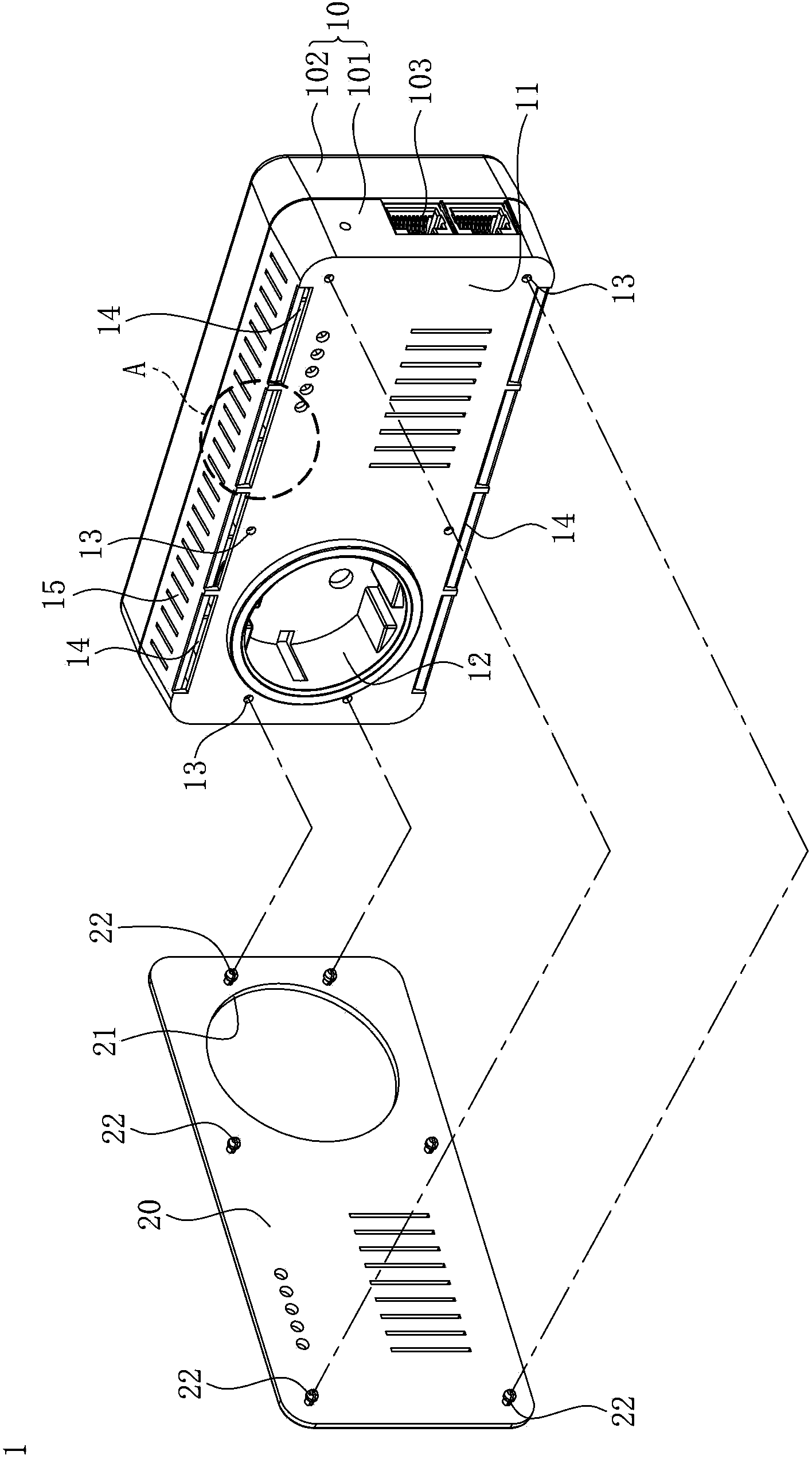
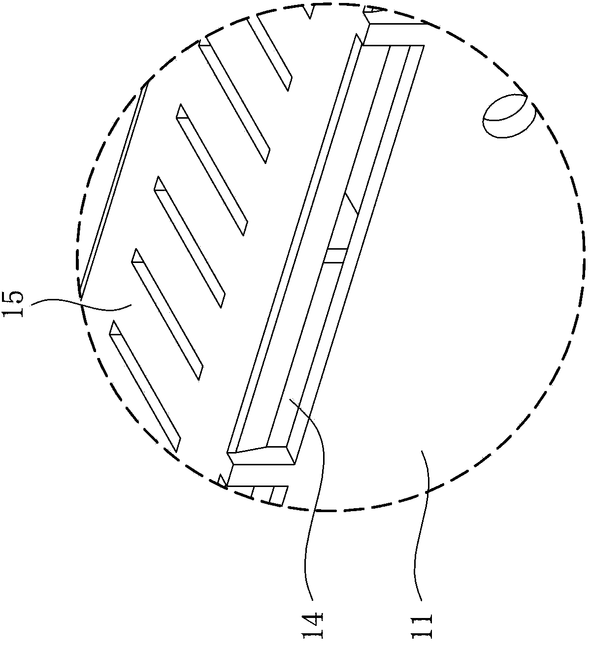
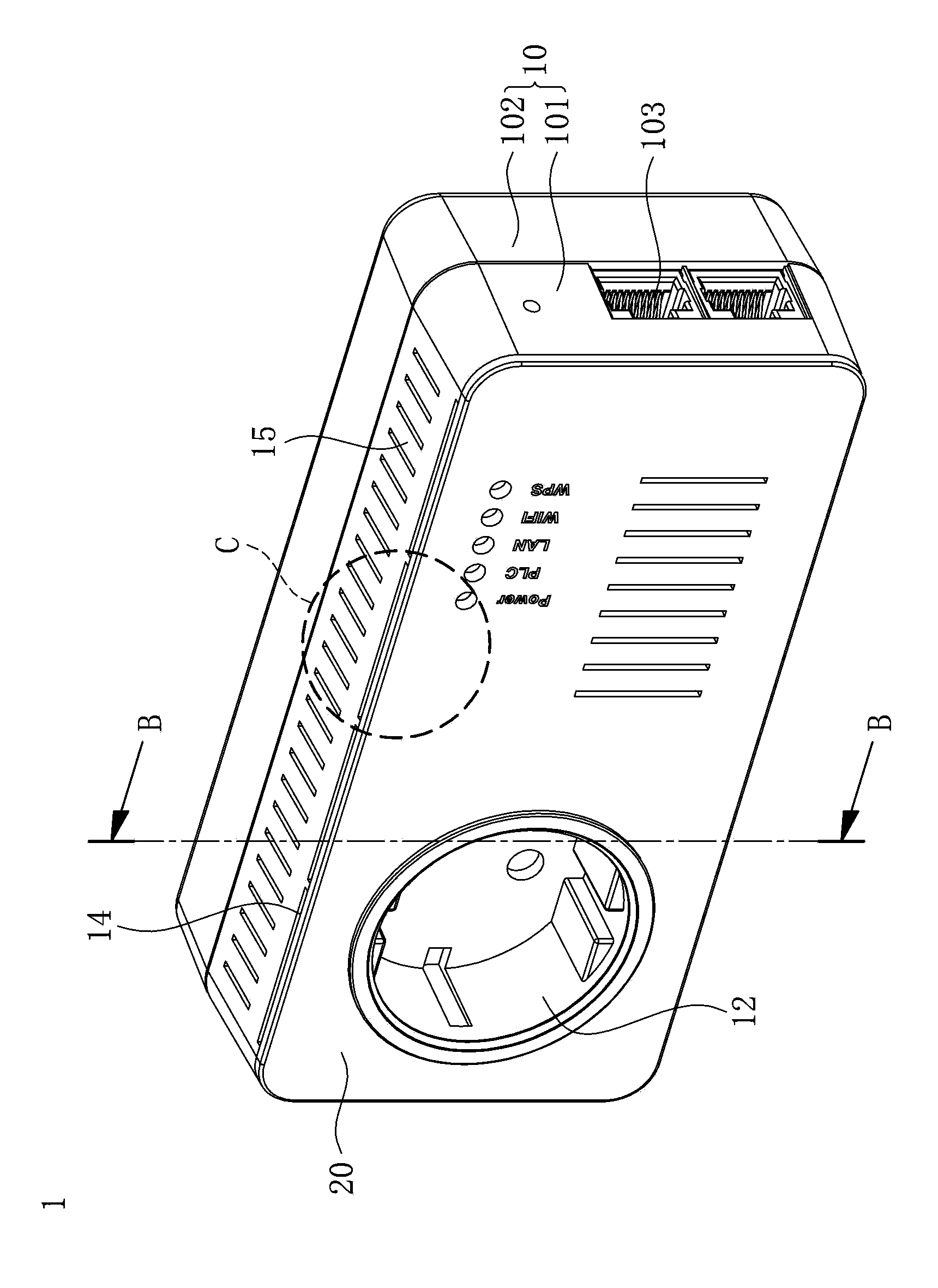
[0038] Please refer to Figure 1A to Figure 3 , Figure 1A It is an exploded schematic diagram of the main body and panel of the power line network device in the embodiment of the present invention; Figure 1B for Figure 1A An enlarged schematic diagram of part A of a power line network device; Figure 2A It is a schematic diagram of a power line network device with a replaceable panel structure according to an embodiment of the present invention; Figure 2B for Figure 2A An enlarged schematic diagram of part C of the power line network device; image 3 for Figure 2A The cross-sectional view of the first housing and the second housing of the medium power line network device along the B-B direction.

[0039] The power line net...


PUM


Abstract

A HomePlug having a panel replacement structure includes a HomePlug body and a panel. The HomePlug body has an operation side and a network port. The operation side has an insertion portion and a first coupling portion. The panel has an opening and second coupling portion. The second coupling portion can be coupled to the first coupling portion so as to allow the opening to correspond in position to the insertion portion. Changes in the appearance of the HomePlug are brought about by panel replacement. A heat dissipation vent is disposed at the junction of the operation side and an adjacent side, such that heat dissipation takes place at the adjacent side-neighboring portion of the heat dissipation vent when the panel is coupled to the operation side and covers the operation side.

Description

technical field [0001] The invention relates to a power line network device, in particular to a power line network device which can achieve different changes by replacing different types of panels. Background technique [0002] The power line network device (Home Plug standard) is a device that uses power line communication technology (Power Line Communication, PLC) to perform Internet browsing and data transmission. Communication network, therefore, the power line communication technology does not need to establish an additional line network to establish a new communication network such as VDSL / ADSL broadband technology, allowing users to directly install the power line network device directly on the indoor AC power socket, and use such as computers, Electronic devices such as mobile phones can perform data transmission after being plugged into the power line network device, and have the technical effect of allowing multiple connected devices to communicate with each other,...

Claims


Application Information

Patent Timeline
IPC IPC(8): H04L12/02H04B3/54H05K7/20
CPCH04L12/10H05K5/0017H04B3/54H04L12/02H02G3/08
Inventor 彭瀞仪罗仕博
Owner ASKEY COMP
Features
  • R&D
  • Intellectual Property
  • Life Sciences
  • Materials
  • Tech Scout
  • Unparalleled Data Quality
  • Higher Quality Content
  • 60% Fewer Hallucinations
Learn More