Three-dimensional posture correcting learning table

A study table and posture correction technology, applied in the field of study table, can solve the problem that study table can not help people to correct study posture in time, and achieve the effect of correcting bad study habits, easy to use, and protecting cervical vertebra.

Active Publication Date: 2014-01-08
郭亮
9 Cites 3 Cited by

AI-Extracted Technical Summary

Problems solved by technology

[0003] The purpose of the present invention is to overcome the defects that the existing learning desks cannot help people correct their learning postures in a timely manner, and provide ...

Abstract

The invention provides a three-dimensional posture correcting learning table which comprises a table top, a telescopic right supporting leg, a bookcase also used as a left supporting leg and a two-dimensional posture correcting learning supply. The two-dimensional posture correcting learning supply comprises a base, a support fixedly connected with the base, a stand column sleeve tube with the lower end fixedly connected with the support and a stand column with the lower end movably connected with the upper end of the stand column sleeve tube, a view window frame is arranged at the upper end of the stand column, a protruding block is arranged on the lower portion of the base, the support can drive the stand column sleeve tube to rotate, and the view window frame can rotate relative to the stand column. An inserting groove seat is fixedly arranged in the middle of the front end of the table top, an inserting groove is formed in the inserting groove seat, and the protruding block is inserted into the inserting groove, so that the two-dimensional posture correcting learning supply is arranged on the table top. Through the structure, a user can correct the sitting posture, a certain distance between the eyes of the user and books is guaranteed, the head the neck incline forwards to maintain a proper angle, and therefore the aim of posture correction is achieved, the health of the user is guaranteed, and the learning table is simple in structure and convenient to use.

Application Domain

Technology Topic

Sitting posturePosture correction +1

Image

  • Three-dimensional posture correcting learning table
  • Three-dimensional posture correcting learning table
  • Three-dimensional posture correcting learning table

Examples

  • Experimental program(1)

Example Embodiment

[0022] The present invention will be further described below in conjunction with accompanying drawing and by best implementation mode:
[0023] see figure 1 — Figure 4 :
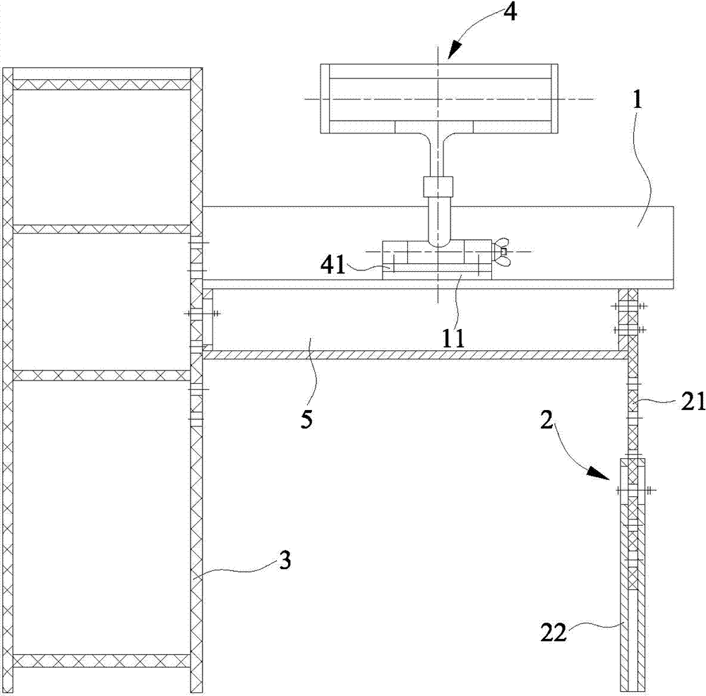
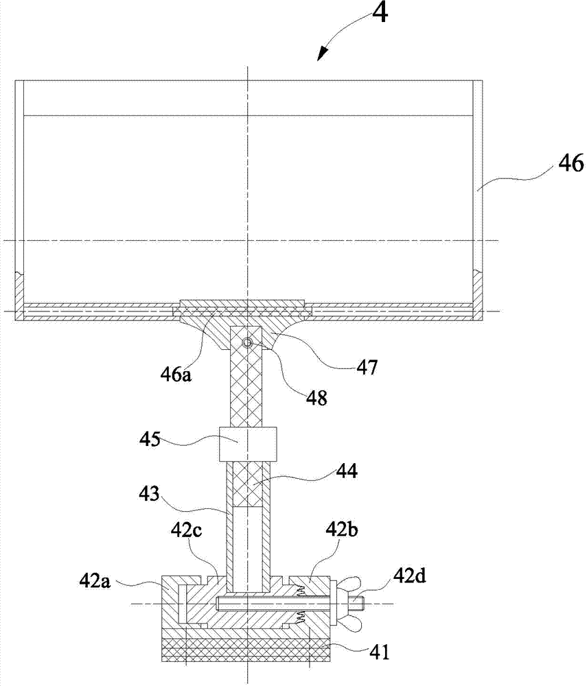
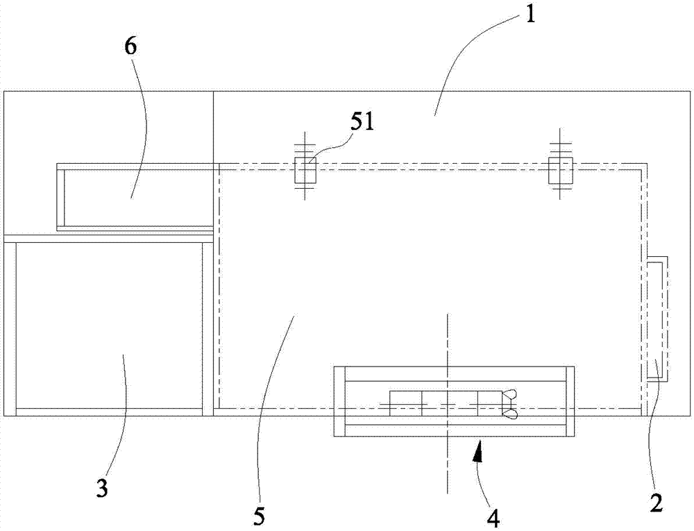
[0024] A three-dimensional posture correction study table, including a desktop 1, a retractable right leg 2, a bookcase 3 that doubles as a left leg, a file box 5 that doubles as a desktop support, and a two-dimensional posture correction learning tool 4;
[0025] The middle part of the front end of the desktop 1 is fixed with a slot seat 11, and a slot is arranged on the slot seat 11, and the slot is an inverted T-shaped slot.
[0026] Described right supporting leg 2 is made up of adjustment plate 21 and adjustment seat 22, and adjustment plate 22 is a rectangular plate, and two rows of altogether sixteen small holes are distributed on the adjustment plate 21, and adjustment seat 21 is the rectangular box of upper end opening, and adjustment seat There is a waist-shaped hole at the upper end of the 22, and the lower end of the adjustment plate 21 is located in the adjustment seat 22, which can move up and down relative to the adjustment seat 22, and is fixed through the waist-shaped hole with a bolt. The small hole can be used for coarse adjustment of the height of the right support leg 2. Shaped holes for fine adjustment;
[0027] There are two rows of twelve holes equally distributed with the right leg holes on the right side plate of the bookcase 3;
[0028] The right side of the file box 5 is fixedly connected with the adjusting plate 21 of the right leg 2 by two bolts, and there is a waist-shaped hole on the left side plate of the file box 5, and the bolt passes through the waist-shaped hole and the small hole on the bookcase 2. File box 5 left side is connected with bookcase 2, and the small hole on the bookcase 2 is used for the rough adjustment of file box 5 height, and the waist shape hole on the file box 5 is used for fine-tuning; File box 5 rear side is fixed with adjustment bracket 51, adjusts There is a waist-shaped hole in the middle of the bracket 51. The bolt passes through the waist-shaped hole to connect the file box 5 with the adjustment bracket 51. The adjustment bracket 51 can move up and down. It can be lifted up, and the inclination of the desktop 1 can also be adjusted by moving the adjustment bracket 5 up and down;
[0029] Bookcase 3 rear side is also provided with desk lamp frame 6, and desk lamp frame 6 one ends are fixed on the base plate of file box 5, can move along with file box 5 moving up and down.
[0030] Described two-dimensional posture correcting learning appliance 4 comprises base 41, the support 42 that is fixedly connected with base 41, the column casing 43 that lower end is fixedly connected with support 42, the column 44 that lower end is movably connected with column casing 43 upper end, column There is a window frame 46 at the upper end of the 44, and the support 42 can drive the column casing 43 to rotate, and the window frame 46 can rotate relative to the column 44;
[0031] The base 41 is a rectangular block, the bottom of the base 41 has a projection 41a, and the projection 41a is an inverted T-shaped tenon; the projection 41a is inserted into the slot of the slot seat 11, so that the two-dimensional posture correcting learning tool 4 and the desktop 1 connect;
[0032] Described bearing 42 comprises left bearing 42a, right bearing 42b and rotating body 42c, and left bearing 42a is cylindrical shape, and left bearing 42a right end has first hole; Right bearing 42b right end is cylinder, and left end is Concave block, semicircular groove is arranged on the concave block, the cylinder left end of right support 42b has the second hole, and the second hole is embedded with the first plane toothed disc, the cylinder right end of right support 42b is opened There is a through hole, and the through hole communicates with the second hole; the left support 42a and the right support 42b are fixed on the base 41; the rotating body 42c is a stepped cylinder with small ends and a large middle, and the right end of the rotating body 42c is embedded with a second plane Sprocket, the second flat toothed disk is compatible with the first flat toothed disk, the left end of the rotating body 42c is matched with the shaft hole of the first hole, the right end of the rotating body 42c is matched with the shaft hole of the second hole, and the left support 42a is fixed on the right support In the groove at the left end of the seat 42b, the rotating body 42c is located in the groove at the left end of the right support 42b, and can rotate in the groove; the adjusting screw 42d runs through the through hole of the right support 42b, and is fixedly connected with the rotating body 42c, There is a wing nut at the right end of the adjusting screw 42d, and there is a spacer between the wing nut and the right support 42b. By rotating the wing nut, the rotating body 42c can be moved left and right, so that the second plane gear plate at the right end of the rotating body 42c is aligned with the right side. The first plane toothed discs of the support 42b are separated or matched to realize the rotation or positioning of the rotating body 42c;
[0033] The column sleeve 43 is a semicircular tube with an open upper end, and the column sleeve 43 is fixed in the middle of the rotating body 42c, so that when the rotating body 42c rotates, it can drive the column sleeve 43 to rotate, so that the column sleeve 43 and the desktop 1 form a clamp horn;
[0034] The cross-sectional shape of the column 44 is semicircular, and the lower end of the column 44 is located in the column sleeve 43; the top of the column sleeve 43 has a special-shaped tube locker 45, and the column 44 passes through the special-shaped tube locker 45 and the upper end of the column sleeve 43 connected, the special-shaped pipe locker 45 can lock the column 44 on the column casing 43;
[0035] The window frame 46 is spliced ​​by two cylindrical plastic tubes and two sheet plastic plates. The window frame 46 is generally rectangular in shape, and a shaft 46a is fixed in the middle of one of the plastic tubes. The outer diameter of the shaft 46a is equal to the inner diameter of the plastic tube. Axle 46a penetrates in the clamping seat 47 of the window, and can rotate in the clamping seat 47 of the window, the internal diameter of the clamping seat 47 of the window is less than the outer diameter of the plastic pipe, and the upper end of the column 44 is fixed on the clamping seat 47 of the window, and the clamping seat of the window There are bolts 48 on the tight seat 47, and butterfly lock nuts are arranged on the bolts 48. The tightness of the window tightening seat 47 can be adjusted by the butterfly lock nuts. When the window frame 46 needs to be rotated, the lock nuts can be loosened; When the window frame 46 needs to be positioned, just tighten the locking nut.
[0036] The above descriptions are only the best embodiments of the present invention. It should be pointed out that for those skilled in the art, without departing from the principle of the present invention, some modifications or equivalent replacements can be made to the technical solution of the present invention, and these should also be regarded as belonging to the protection scope of the present invention. For example, a drawer is installed under the file box; under the condition that the user is prevented from lying down, the shape of the window frame can be other suitable shapes, such as oval; It can be in other forms, such as the threaded connection between the lower end of the column and the upper end of the column sleeve; under the condition that the positioning of the column and the column sleeve can be ensured, the special-shaped pipe locker can also be replaced with other locking devices.

PUM

no PUM

Description & Claims & Application Information

We can also present the details of the Description, Claims and Application information to help users get a comprehensive understanding of the technical details of the patent, such as background art, summary of invention, brief description of drawings, description of embodiments, and other original content. On the other hand, users can also determine the specific scope of protection of the technology through the list of claims; as well as understand the changes in the life cycle of the technology with the presentation of the patent timeline. Login to view more.

Similar technology patents

Adaptive canceller for frequency reuse systems

ActiveUS6859641B2Effective and efficient mannerEasy to useRadio transmissionTransmission noise suppressionSignal of interestSatellite
Owner:RAYTHEON APPLIED SIGNAL TECH

Utilization of podcasts on portable media devices

InactiveUS20060265637A1Easy to useDigital data information retrievalUsing non-detectable carrier informationMediaFLOMetadata
Owner:APPLE INC

Classification and recommendation of technical efficacy words

  • Reduce fatigue
  • Easy to use

Dictation selection

ActiveUS8032372B1Reduce fatigueReduce physical stressNatural language translationComputer-assisted medical data acquisitionMedical transcriptionFeature set
Owner:DELIVERHEALTH SOLUTIONS LLC

Locking hinge connector apparatus

InactiveUS20060016047A1Reduce back strainReduce fatigueBrush bodiesHingesHinge angleEngineering
Owner:BLACKMAN GARY PALMER +1

Laser assisted total joint arthroplasty

InactiveUS20090234360A1Easy to useNon-surgical orthopedic devicesSurgical sawsLaser assistedLaser guidance
Owner:ALEXANDER VLADIMIR

System, method, and apparatus for settlement for participation in an electric power grid

ActiveUS8583520B1Communication securityEasy to useLevel controlCoin-freed apparatusNetwork managementGrid operator
Owner:CAUSAM ENERGY INC
Why Eureka
Try Eureka