Improved power transmission line lightning stroke double-end traveling wave positioning method

A double-ended traveling wave positioning and transmission line technology, applied in the direction of the fault location, etc., can solve the problems of the influence of positioning accuracy, no consideration of attenuation and deformation, and insufficient practicability of the positioning method

Active Publication Date: 2014-01-08
YUN NAN ELECTRIC TEST & RES INST GRP CO LTD ELECTRIC INST +1
View PDF7 Cites 13 Cited by
  • Summary
  • Abstract
  • Description
  • Claims
  • Application Information

AI Technical Summary

Problems solved by technology

The main disadvantages of this method are: ①The analysis and calculation is carried out by collecting the traveling wave signals at the busbars at both ends of the line, without considering the attenuation caused by the fault transient traveling wave current caused by lightning strikes in the actual situation due to long-distance transmission to the busbars on both sides The calculation using this method will reduce the accuracy of lightning strike location; ②Because the traditional double-terminal fault distance measuring device cannot eliminate the interference of power frequency signals, and the lack of a method for distinguishing line short-circuit faults from lightning strike faults in this paper, the positioning method is not practical enough; ③In this paper, the influence of coupling between the three-phase lines is not considered, and the analysis of the traveling wave of the lightning strike phase lines directly will have a certain impact on the positioning accuracy

Method used


Image

  • Improved power transmission line lightning stroke double-end traveling wave positioning method
  • Improved power transmission line lightning stroke double-end traveling wave positioning method
  • Improved power transmission line lightning stroke double-end traveling wave positioning method

Examples


Embodiment 1

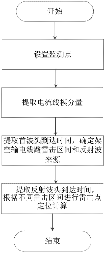
[0052] like figure 1 , 2 As shown, taking a 110kV, 60km overhead transmission line as an example, an improved transmission line lightning strike double-terminal traveling wave positioning method, the specific steps of the method are as follows:

[0053] (1) Set monitoring points

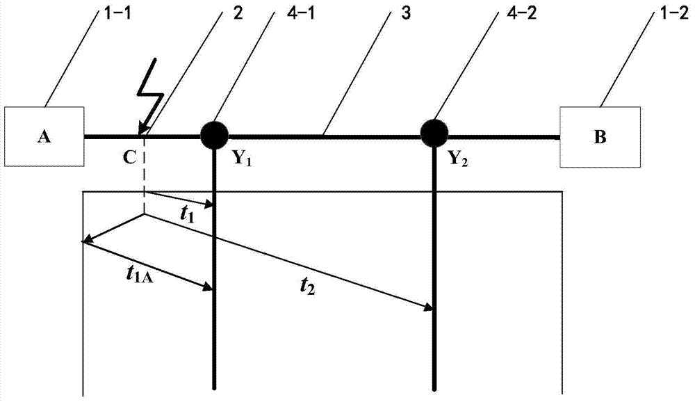
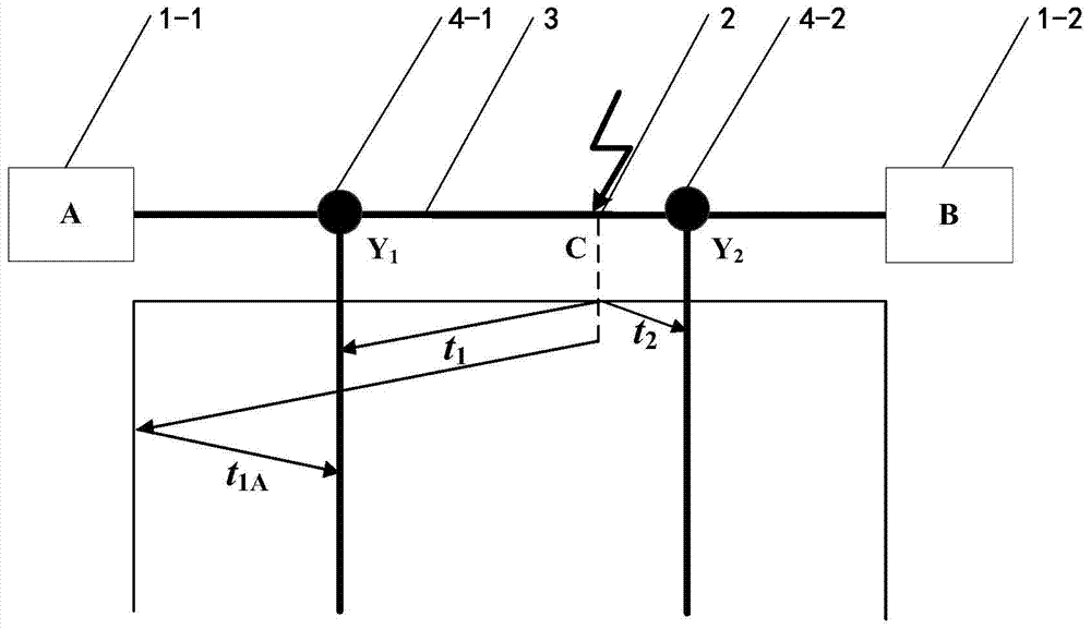
[0054] First, set up two monitoring points Y on the overhead transmission line 1 and Y 2 . The two monitoring points Y 1 and Y 2 It is installed at both ends of the overhead transmission line and distributed symmetrically. Each monitoring point Y 1 or Y 2 The average distance from the nearest substation is 10km, and the substation A on the left is set to the monitoring point Y 1 Between is monitoring area 1, monitoring point Y 2 To the right substation B is monitoring area 2, monitoring point Y 1 to monitoring point Y 2 The monitoring area 3 is in between.

[0055] (2) Extract the current line mode component

[0056] After step (1) is completed, set the distance between lightning strike ...

Embodiment 2

[0073] Such as figure 1 , 3 As shown, an improved transmission line lightning strike double-terminal traveling wave positioning method is the same as in embodiment 1, wherein:

[0074] In step (2), set the distance between lightning strike point C and substation A on the left as 42.6km.

[0075] Monitoring point Y 1 The line-mode component of the current at x 1 Calculated as Figure 7 Shown, monitoring point Y 2 The line-mode component of the current at x 1 Calculated as Figure 8 shown.

[0076] In step (3), use wavelet transform to extract monitoring points Y respectively 1 and Y 2 The line-mode component of the current at x 1 Arrival time of the first wave in the medium, that is, t 1 109.5μs, t 2 is 25.4μs.

[0077] Then compare the monitoring point Y 1 and monitoring point Y 2 The line-mode component of the current at x 1 The polarity of the first wave head to determine the lightning strike interval: such as Figure 7 , 8 Shown, monitoring point Y 1 and ...

Embodiment 3

[0087] Such as figure 1 , 4 As shown, an improved transmission line lightning strike double-terminal traveling wave positioning method is the same as in embodiment 1, wherein:

[0088] In step (2), set the distance between lightning strike point C and substation A on the left as 57.4km.

[0089] Monitoring point Y 1 The line-mode component of the current at x 1 Calculated as Figure 9 Shown, monitoring point Y 2 The line-mode component of the current at x 1 Calculated as Figure 10 shown.

[0090] In step (3), use wavelet transform to extract monitoring points Y respectively 1 and Y 2 The line-mode component of the current at x 1 Arrival time of the first wave in the medium, that is, t 1 149.6μs, t 2 is 15.9μs.

[0091] Then compare the monitoring point Y 1 and monitoring point Y 2 The line-mode component of the current at x 1 The polarity of the first wave head to determine the lightning strike interval: such as Figure 9 , 10 Shown, monitoring point Y 1 an...


PUM


Abstract

The invention provides an improved power transmission line lightning stroke double-end traveling wave positioning method, and relates to an overhead transmission line lightning stroke fault positioning calculation method. A computer is utilized, through program, the lightning stroke fault point position on an overhead transmission line is determined through setting monitoring points, extracting current line model components, extracting the first wave head reaching time, determining the overhead transmission line lightning stroke interval and reflecting wave sources, extending the reflecting wave head reaching time and carrying out lightning stroke point positioning calculation according to different lightning stroke intervals. The method provided by the invention has the characteristics that simplicity and feasibility are realized, the positioning precision is high, the positioning efficiency is high, the practicability is high, the lightning stroke fault points on the overhead transmission line can be fast and accurately judged, the popularization and the application are convenient, and the like. The method provided by the invention can be widely applied to the lightning positioning calculation of the overhead transmission line, and is particularly suitable for the lightning positioning calculation of the high-voltage overhead transmission line with the voltage being 110kV and higher.

Description

technical field [0001] The invention belongs to the technical field of distance measurement for overhead transmission line faults, and in particular relates to a lightning strike fault location calculation method for overhead transmission lines. Background technique [0002] High-voltage overhead transmission lines are an important part of the power system. They are widely distributed, crisscross, and stretch for hundreds or even thousands of kilometers, so they are extremely vulnerable to lightning strikes. Statistics show that the number of trips caused by lightning strikes on high-voltage overhead transmission lines in my country accounts for 40% to 70% of the total number of trips in operation. high. When lightning strikes the overhead transmission line, it may cause the line switch to trip and cause a power outage, and it will also cause damage to electrical equipment, and even lead to vicious accidents such as the collapse of the power system, causing huge economic los...

Claims


Application Information

Patent Timeline
Patent Type & Authority Applications(China)
IPC IPC(8): G01R31/08
Inventor 马仪申元王磊姚陈果吴昊王琪米彦
Owner YUN NAN ELECTRIC TEST & RES INST GRP CO LTD ELECTRIC INST
Why Eureka
Try Eureka