Hinge sleeve pipe and punching mould and production process of hinge sleeve pipe

A technology for stamping dies and bushings, which is applied in forming tools, manufacturing tools, metal processing equipment, etc. It can solve problems such as uneven distribution of chamfers and affect the appearance and quality of hinge bushings, achieve uniform distribution, improve appearance and quality , to ensure the effect of stamping accuracy

Inactive Publication Date: 2014-01-15
吉林博仁科技有限责任公司
View PDF9 Cites 3 Cited by
  • Summary
  • Abstract
  • Description
  • Claims
  • Application Information

AI Technical Summary

Problems solved by technology

[0004] In the above process, since the chamfer is formed by turning on a lathe, due to factors such as machining errors and position errors, there are often large differences in shape and size between different chamfers on the same hinge sleeve or different hinge sleeves. The position error makes the distribution of the chamfer on the hinge bushing uneven, which affects the appearance and quality of the hinge bushing

Method used


Image

  • Hinge sleeve pipe and punching mould and production process of hinge sleeve pipe
  • Hinge sleeve pipe and punching mould and production process of hinge sleeve pipe
  • Hinge sleeve pipe and punching mould and production process of hinge sleeve pipe

Examples


Embodiment Construction

[0035] The invention provides a stamping die for a hinge sleeve, which avoids the uneven distribution of chamfers on the hinge sleeve and improves the appearance and quality of the hinge sleeve.

[0036] The following will clearly and completely describe the technical solutions in the embodiments of the present invention with reference to the accompanying drawings in the embodiments of the present invention. Obviously, the described embodiments are only some, not all, embodiments of the present invention. Based on the embodiments of the present invention, all other embodiments obtained by persons of ordinary skill in the art without making creative efforts belong to the protection scope of the present invention.

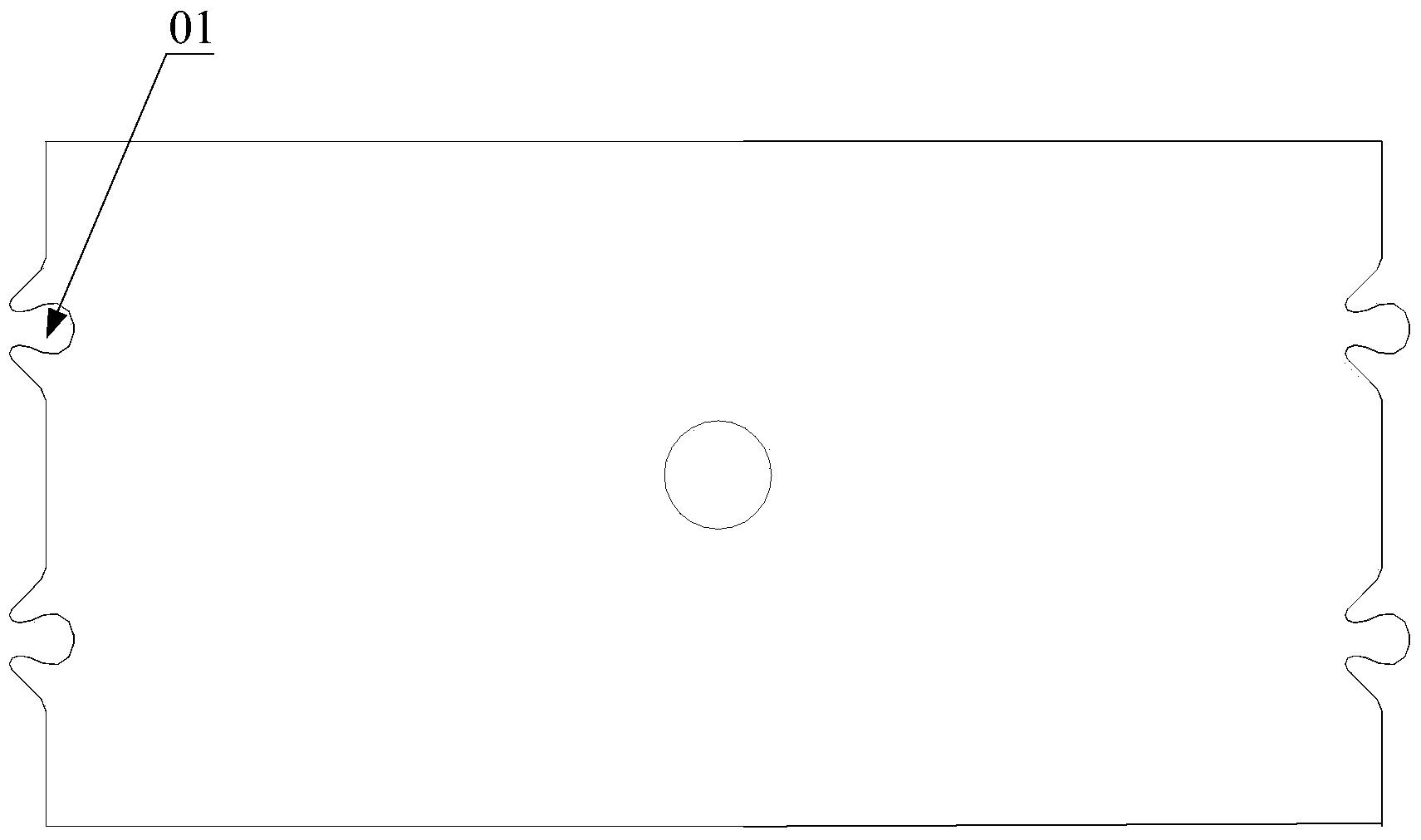
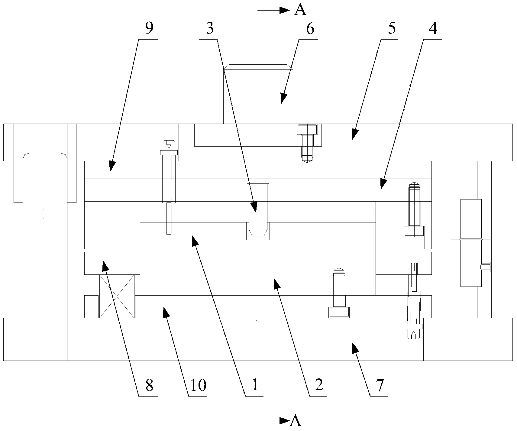
[0037] like image 3 and Figure 4 As shown, the stamping die of the hinge sleeve provided by the embodiment of the present invention is used to press the chamfer on the semi-finished part of the hinge sleeve, which includes:

[0038] Upper punch 1;

[0039] A low...


PUM


Abstract

The invention provides a punching mould of a hinge sleeve pipe. The punching mould of the hinge sleeve pipe is used for manufacturing chamfers on a semi-finished product of the hinge sleeve pipe in a pressing mode and comprises an upper convex mould, a lower concave mould and a punch head, wherein the lower concave mould can be matched with the upper convex mould to position the semi-finished product, and the punch head is connected with the upper convex mould. The punching mould of the hinge sleeve pipe guarantees the chamfering shape and the punching accuracy of positions, avoids shape errors and position errors, enables the chamfers to be distributed on the hinge sleeve pipe more evenly, and improves the appearance quality of the hinge sleeve pipe. The invention further provides a production process of the hinge sleeve pipe by means of the punching mould and the hinge sleeve pipe manufactured through the production process.

Description

technical field [0001] The present invention relates to the technical field of auto parts, and more specifically, relates to a stamping die for a hinge sleeve. A hinge sleeve manufactured by craftsmanship. Background technique [0002] The hinge sleeve is an important part of the car subframe, which is used to connect the rear axle of the car and the shock absorbing spring, and mainly plays the role of connection and support. [0003] In the prior art, the production process of the hinge sleeve is as follows: use a stamping die to blank and punch the plate, and use a lathe to turn a plurality of chamfers on the two sides of the material for mutual connection, such as figure 1 As shown, so that the two sides can be clamped in the subsequent process, and then the material is preformed, so that the material has the shape and outline of the hinge sleeve before rolling, and the material is rolled so that it has The two sides of the chamfer are brought into contact and eventuall...

Claims


Application Information

Patent Timeline
Patent Type & Authority Applications(China)
IPC IPC(8): B21D37/10B21D35/00
Inventor 姜红宋桢杨艳红
Owner 吉林博仁科技有限责任公司
Why Eureka
Try Eureka