Traction buffering device

A technology for traction buffering and tailstock installation, which is used in traction devices, transportation and packaging, railway car body components, etc., can solve the problems of reducing the safety and reliability of the device, short life of rubber buffers, and increasing production costs, and achieves a compact structure. , The effect of improving the service life and reducing the difficulty of installation

Active Publication Date: 2014-01-15
QINGDAO SRI TECH CO LTD
View PDF6 Cites 18 Cited by
  • Summary
  • Abstract
  • Description
  • Claims
  • Application Information

AI Technical Summary

Problems solved by technology

Its main disadvantage is that the combined buffer device is composed of multiple parts, the overall length is long and there are many interfaces, which greatly reduces the safety and reliability of the whole device, and the life of the rubber buffer is short, especially when it is subjected to shearing
The cost of this combination scheme is relatively high, and at the same time, the difficulty of the structure of other parts is increased, which greatly increases the production cost.

Method used


Image

  • Traction buffering device
  • Traction buffering device
  • Traction buffering device

Examples


Embodiment Construction

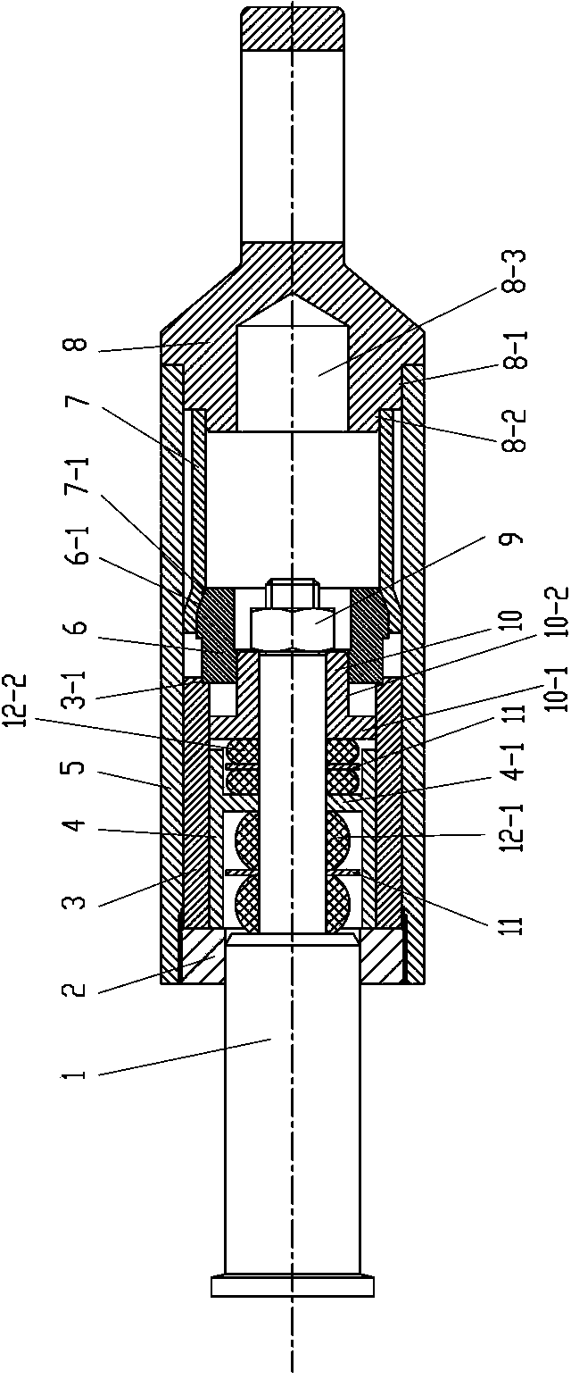
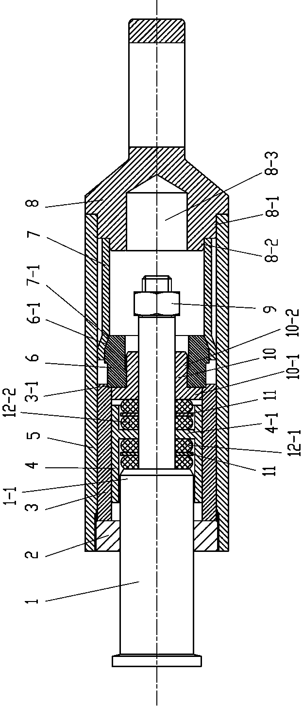
[0019] Such as Figure 1~4 As shown, the first embodiment of the present invention, a traction buffer device, includes an outer shell 5, a tailstock 8, a traction guide rod 1, an end cover 2, a guide partition 10, a lock nut 9 and at least two Elastomer, the two ends of the outer casing 5 are fixedly connected with the end cover 2 and the tailstock 8 respectively, one end of the traction guide rod 1 is inserted in the outer casing 5, and the other end extends out of the outer casing 5, and the guide The partition plate 10 and the elastic body 12-1, 12-2 are all loosely fitted on the rod body of the traction guide rod 1 located in the outer casing 5, and the inner sleeve 3, the sliding sleeve are also housed in the outer casing 5 4. The expansion ring 6 and the deformation tube 7, the left end of the inner sleeve 3 is in contact with the end cover 2, the sliding sleeve 4 is installed in the inner sleeve 3 and its outer circumference is slidably matched with the inner wall of th...


PUM


Abstract

The invention discloses a traction buffering device of a railway vehicle. The traction buffering device comprises an outer shell, an installation tail base, a traction guiding rod, an end cover, a guiding partition plate, a locking nut and at least two elastic bodies. The two ends of the outer shell are fixedly and respectively connected with the end cover and the installation tail base. The outer shell is internally provided with an inner sleeve, a sliding sleeve, an expansion ring and a transformation pipe. The left end of the inner sleeve abuts against the end cover, the sliding sleeve is installed inside the inner sleeve, the periphery of the sliding sleeve is matched with the inner wall of the inner sleeve in a sliding mode, a partition plate is arranged inside the sliding sleeve, the left side of the partition plate abuts against the first elastic body, and the right side of the partition plate abuts against the second elastic body. The guiding partition plate comprises a radial boss and a shaft neck, wherein the periphery of the radial boss is matched with the inner wall of the inner sleeve in a sliding mode, and the periphery of the shaft neck is matched with the inner wall of the expansion ring in a sliding mode. The right end of the expansion ring is provided with a conical surface and is inserted into a left end pipe opening of the transformation pipe, the left end of the expansion ring abuts against the right end of the inner sleeve, and the transformation pipe is fixed on the installation tail base. The traction buffering device has the function of buffering and the function of collision protecting, and is simple in structure.

Description

technical field [0001] The invention relates to a traction buffer protection device for rail vehicles, in particular to a buffer for traction couplers of urban rail vehicles and railway passenger cars. Background technique [0002] The coupler buffer device is one of the important parts of the vehicle, which can transmit and buffer the traction and impact between the vehicles, and it is directly related to the safety and comfort of train operation. The buffers used in rail vehicles are in various forms. According to the different buffer media, there are: rubber buffers, ring spring buffers, crush tubes, gas-hydraulic buffers and various combination types of buffers. At present, more buffers of various combinations are used on urban rail vehicles, especially the combination of crushing pipes and rubber buffers connected with the coupler. Its main disadvantage is that the combined buffer device is composed of many parts, the overall length is long and there are many interface...

Claims


Application Information

Patent Timeline
Patent Type & Authority Applications(China)
IPC IPC(8): B61G9/04
Inventor 吴刚
Owner QINGDAO SRI TECH CO LTD
Why Eureka
Try Eureka