
Traction gear of tentering setting machine

A stenter setting machine and traction device technology, applied in textiles and papermaking, fabric surface trimming, fabric elongation, etc., can solve the problems of space occupation, installation difficulties, and no adjustment mechanism for guide rollers, etc., to reduce height and reduce Occupation of space, convenient and accurate adjustment effect

Inactive Publication Date: 2014-01-15
WUJIANG FUMAO TEXTILE
View PDF7 Cites 2 Cited by
  • Summary
  • Abstract
  • Description
  • Claims
  • Application Information

AI Technical Summary

Problems solved by technology

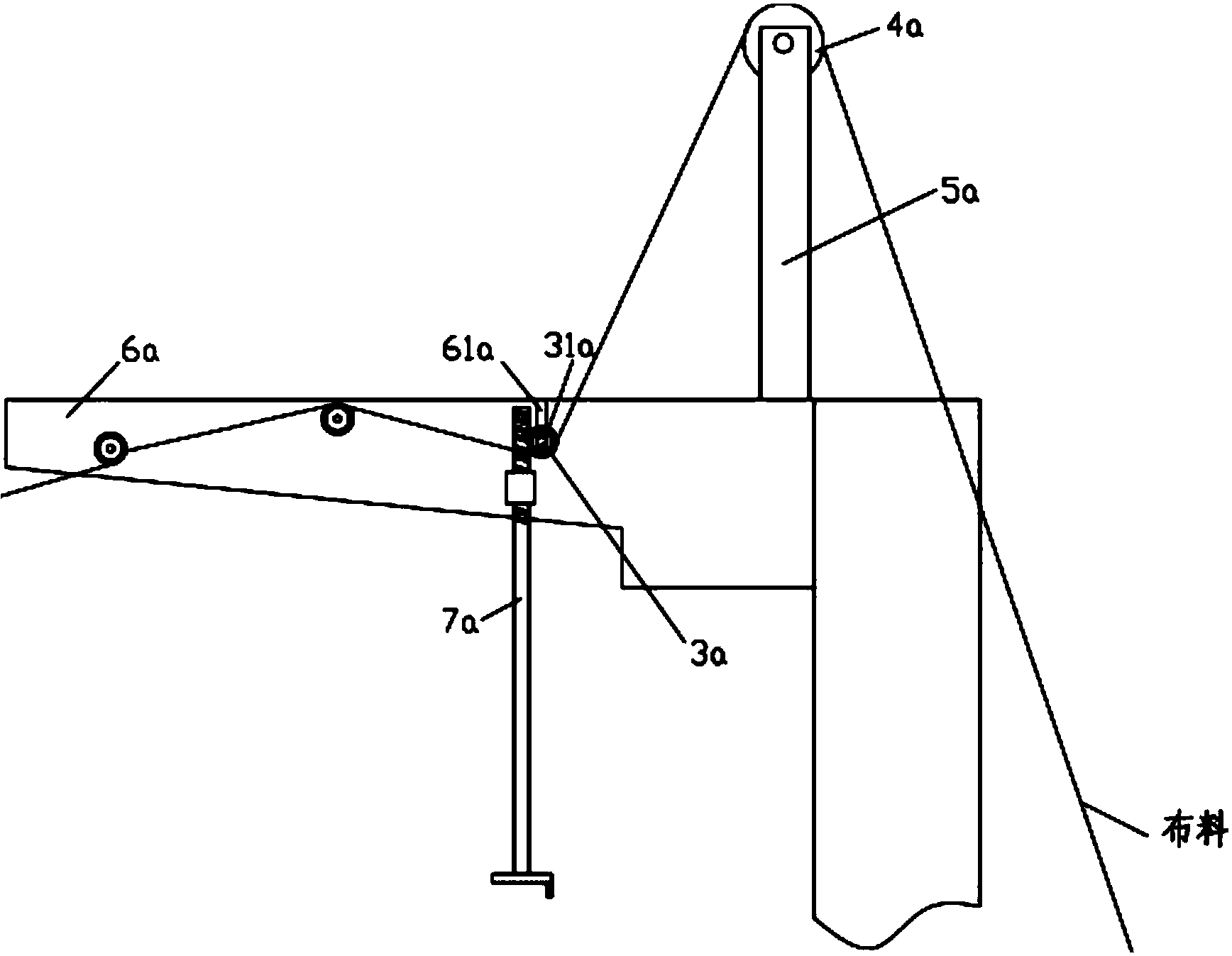
[0002] The traction device of the stenter setting machine is the first process for the cloth to enter, and it includes an open-width cloth feeding device and a rolling device. The existing open-width cloth feeding device has four cloth guide rollers, such as figure 1 As shown, the positions of the first three cloth guide rollers are similar, the fourth cloth guide roller 4a is fixed on the top of the support rod 5a, and the support rod 5a is fixed on the connecting beam 6a, and the support rod 5a is generally higher than the connecting beam 6a by one More than one meter, it is difficult to install and occupies the space above, which makes the factory building must be high. The two ends of the third cloth guide roller 3a are inserted into the slots 61a formed on the two connecting beams 6a, and the third guide roller 3a The two ends of the cloth roller 3a are fixed with gears 31a, and the connecting beam 6a is hinged with a screw rod 7a, the screw rod 7a is meshed with the gear 31a, and the third cloth guide roller 3a is adjusted up and down by rotating the screw rod 7a, which requires manual adjustment ,very troublesome
[0003] The padding device is a mechanism to squeeze out the excess chemical materials in the cloth. The cloth passes through the pressing of the upper roller and the lower roller to squeeze out the excess chemical materials in the cloth. There are guide rollers in front of the upper roller and the lower roller. The roller is the mechanism to guide the cloth and adjust the tension of the cloth. However, the guide roller on the rolling car of the existing stenter setting machine has no adjustment mechanism, which cannot meet the different tensions required by different cloth, and affects the processing of the cloth. quality

Method used


Image

  • Traction gear of tentering setting machine
  • Traction gear of tentering setting machine
  • Traction gear of tentering setting machine

Examples


Embodiment

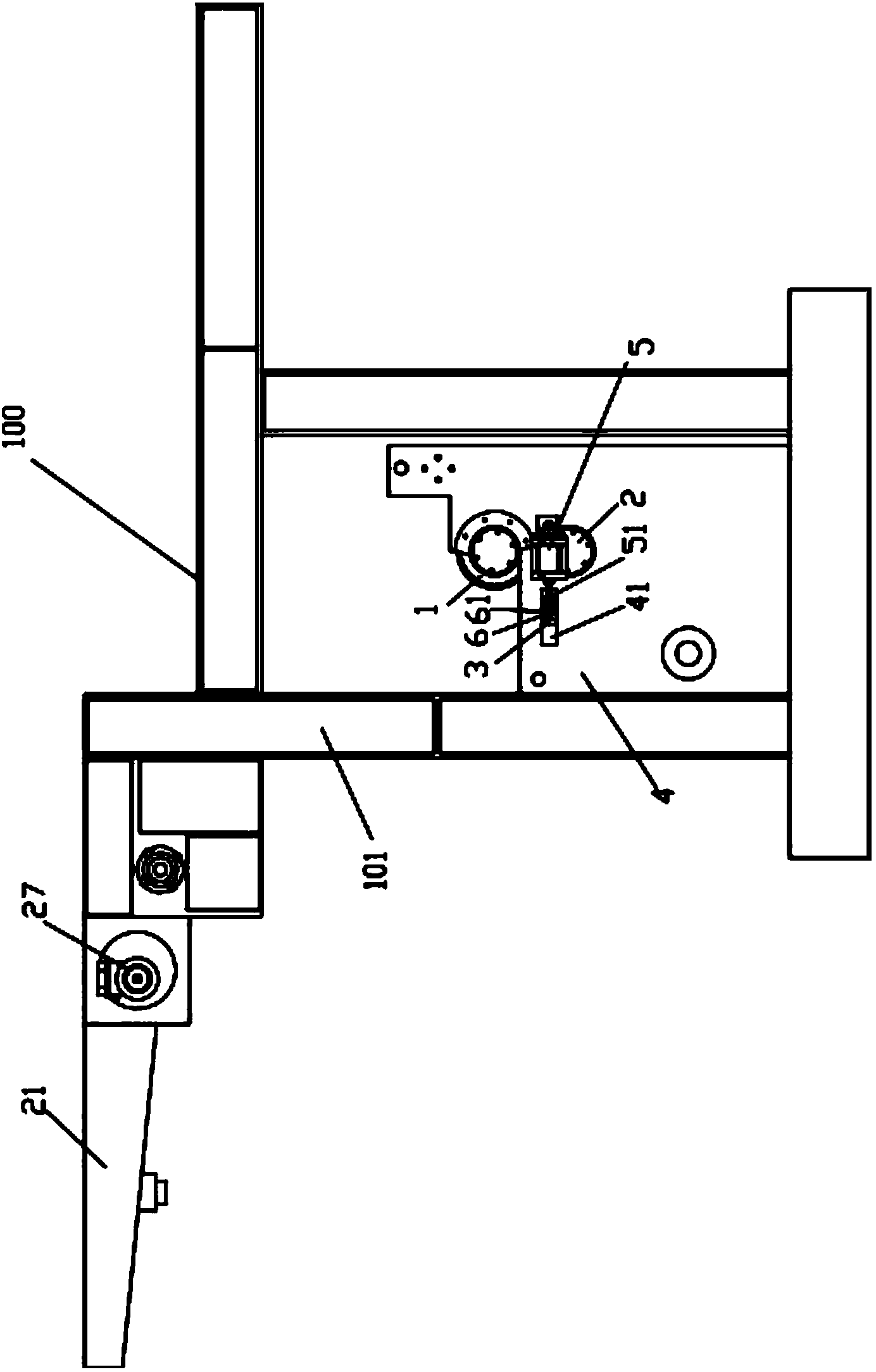
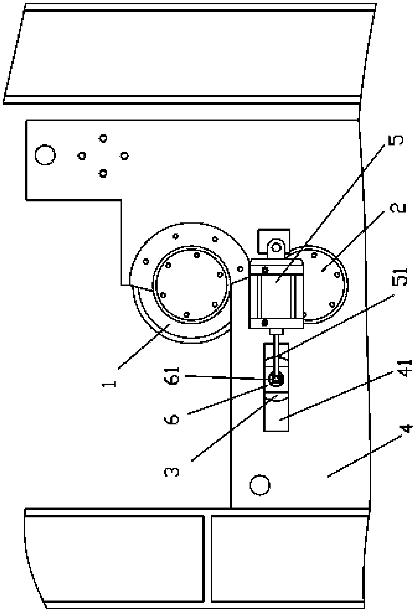
[0022] Example: see Figures 2 to 9 As shown, a drawing device of a stenter setting machine includes a frame 100, an open-width cloth feeding device 20 and a rolling device 10. The structure of the open-width cloth feeding device 20 is that the connecting beam 21 is fixed on the front pillar 101 of the frame 100 On the upper part, the first cloth guide roller 22 and the second cloth guide roller 23 are hinged between the two connecting beams 21, and the connecting beams 21 on both sides between the first cloth guiding roller 22 and the second cloth guiding roller 23 are fixed There are push cylinders 24, and the push rods 241 of two push cylinders 24 are hinged at the two ends of the cloth guide roller 25 in the middle; Both ends of the roll 3 are arranged on the two side plates 4 of the frame 100, the guide roll 3 is in front of the lower roll 2, the two side plates 4 are respectively fixed with a cylinder 5, and one end of the push rod 51 of the cylinder 5 is hinged on the g...


PUM


Abstract

The invention discloses a traction gear of a tentering setting machine. An open-width cloth-feeding device structure is as follows: connecting beams are fixed at the upper parts of front standing pillars of a frame; a first cloth guide roller and a second cloth guide roller are hinged between the two connecting beams; pushing cylinders are fixed on the connecting beams on the two sides of the first cloth guide roller as well as the second cloth guide roller and between the first cloth guide roller and the second cloth guide roller; catch bars of the two pushing cylinders are hinged to two ends of a middle cloth guide roller. A padder device comprises a roller, a lower roller and a guide roller, wherein the two ends of the guide roller, the two ends of the lower roller and the two ends of the guide roller are all arranged on two side plates of the frame; the guide roller is located in front of the lower roller; cylinders are respectively fixed on the two side plates; one end of the push rod of each cylinder is hinged to a roll shaft end part of the guide roller; the two end parts of the roll shaft of the guide roller are respectively arranged sliding through grooves which are formed in the two side plates respectively. The middle cloth guide roller can be adjusted conveniently and accurately through the pushing cylinders; the roll shaft of the guide roller is pushed by the push rods of the cylinders to adjust the position of the guide rail on the side plates, so as to adjust the tension of cloth during processing and meet the requirement of tension of different cloth during processing.

Description

Technical field: [0001] The invention relates to the technical field of a stenter setting machine, and more specifically relates to a drawing device of a stenter setting machine. Background technique: [0002] The traction device of the stenter setting machine is the first process for the cloth to enter, and it includes an open-width cloth feeding device and a rolling device. The existing open-width cloth feeding device has four cloth guide rollers, such as figure 1 As shown, the positions of the first three cloth guide rollers are similar, the fourth cloth guide roller 4a is fixed on the top of the support rod 5a, and the support rod 5a is fixed on the connecting beam 6a, and the support rod 5a is generally higher than the connecting beam 6a by one More than one meter, it is difficult to install and occupies the space above, which makes the factory building must be high. The two ends of the third cloth guide roller 3a are inserted into the slots 61a formed on the two connec...

Claims


Application Information

Patent Timeline
IPC IPC(8): D06C3/00
Inventor 杨培发
Owner WUJIANG FUMAO TEXTILE
Learn More