Intelligent anti-theft lock of electronic password safe

An electronic password and safe technology, applied in the field of electronic high-tech products, can solve the problems of low safety factor and inconvenience, and achieve the effect of reasonable structure and convenient operation.

Inactive Publication Date: 2014-01-15
安长海
View PDF5 Cites 1 Cited by
  • Summary
  • Abstract
  • Description
  • Claims
  • Application Information

AI Technical Summary

Problems solved by technology

[0002] At present, safes at home and abroad generally use mechanical locks. Mechanical combination locks and key locks all have keyhole problems, leaving thieves with a chance to unlock. The safety factor is low and it is inconvenient.

Method used


Image

  • Intelligent anti-theft lock of electronic password safe

Examples


Embodiment Construction

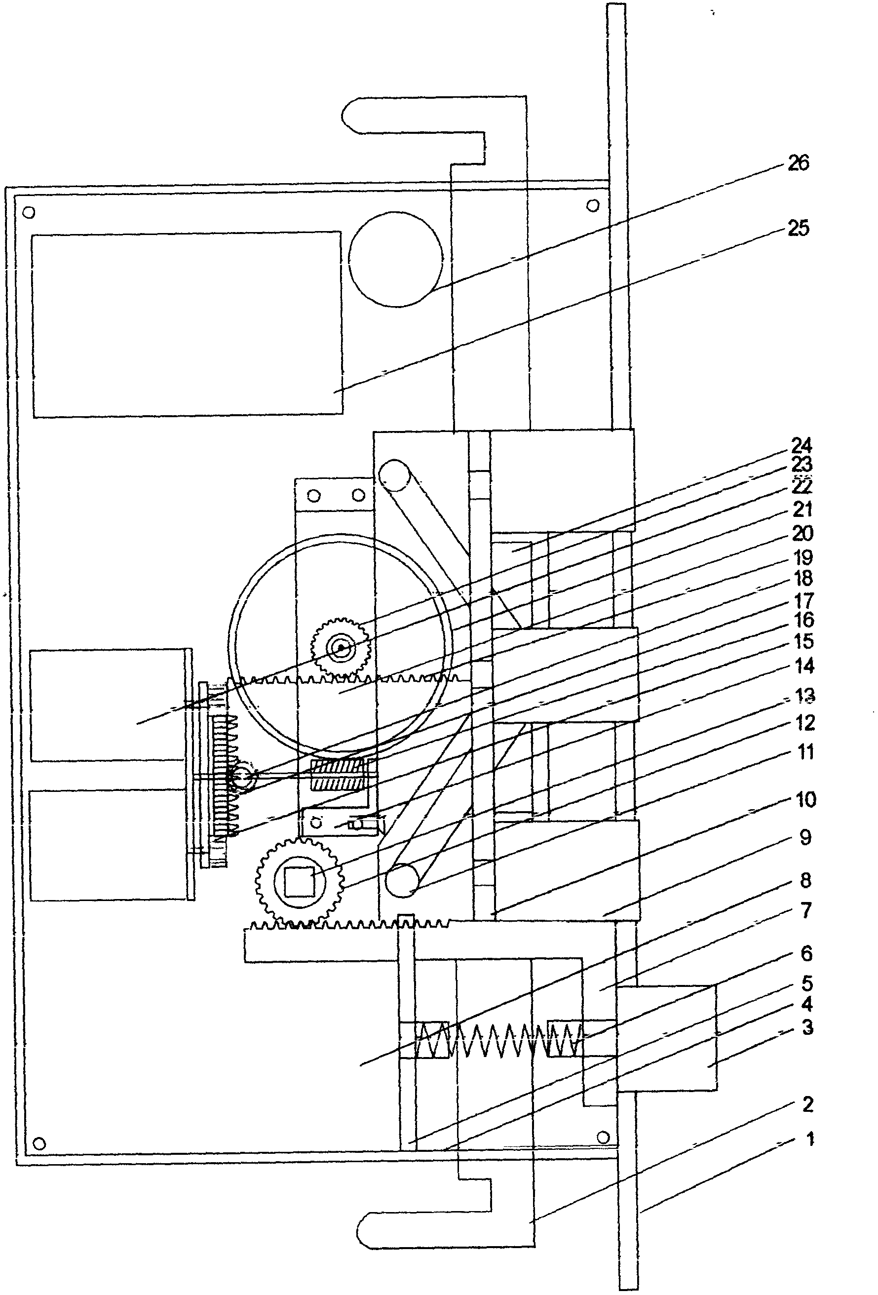
[0008] Provide the present invention example as follows in conjunction with accompanying drawing,

[0009] Such as figure 1 As shown: the lock body assembly 4 of the present invention is provided with multiple groups of micro motors 22 connected with the outer diameter straight tooth end face bevel gear 17, the outer diameter straight tooth end face bevel gear 7 and the worm rod 16 are connected with the turbine mechanism 21, and the transmission wheel mechanism 23 Connect with the anti-theft latch push-pull mechanism 19, the lower end of the anti-theft latch push-pull mechanism 19 and a plurality of anti-theft latch push-pull mechanisms 19 are provided with sliding push-pull pins 11, the slide push-pull pins 11 are inserted into the slide slots of the slide push-pull mechanism 2, slide The 90-degree hook at one end of the garbage pushing mechanism 2 is inserted into the slider 24, the bumper pin 3 is connected to the rack drive mechanism 7, the rack drive mechanism 7 is conne...


PUM


Abstract

The invention discloses an intelligent anti-theft lock of an electronic password safe. The intelligent anti-theft lock of the electronic password safe comprises an electronic password transmitter, a lock pin control end cover, a sliding push-and-pull mechanism, a collision bolt device, a fixed spring mechanism, a sliding push-and-pull pin, a manual collision driving wheel mechanism, a handle insertion hole, a driving wheel support, a motor driving wheel mechanism, an anti-theft bolt push-and-pull mechanism, a driving wheel supporting plate, a sliding groove, a mobile phone emergency number reporting circuit board device and an alarm.

Description

technical field [0001] The invention belongs to an electronic high-tech product, which is an intelligent anti-theft lock for an electronic password safe combined with electronics and machinery. Background technique [0002] At present, safes at home and abroad generally adopt mechanical locks. There are keyhole problems in mechanical combination locks and key locks, leaving opportunities for thieves to unlock the locks. The safety factor is low and it is also inconvenient. Contents of the invention [0003] The purpose of the present invention is to propose a new type of intelligent anti-theft lock for an electronic password safe, which has the advantages of simple structure, elegant design, high safety factor, low manufacturing cost, no keyhole, and no room for thieves. [0004] The object of the present invention can be achieved by adopting the following solutions, including electronic code transmitter, lock pin control end cover, sliding push-pull mechanism, collision l...

Claims


Application Information

Patent Timeline
Patent Type & Authority Applications(China)
IPC IPC(8): E05B65/52E05B47/02E05B63/14E05B45/08
Inventor 安长海
Owner 安长海
Why Eureka
Try Eureka