Adjustable damping valve arrangement

A damping valve and valve body technology, applied in shock absorbers, shock absorbers, springs/shock absorbers, etc., can solve problems such as improving fatigue strength, no diaphragm axial support, etc., to achieve the effect of functional expansion

Inactive Publication Date: 2014-01-15
ZF FRIEDRICHSHAFEN AG
View PDF8 Cites 7 Cited by
  • Summary
  • Abstract
  • Description
  • Claims
  • Application Information

AI Technical Summary

Problems solved by technology

There is also no axial support of the diaphragm to limit the lift stroke and thus increase fatigue strength

Method used


Image

  • Adjustable damping valve arrangement
  • Adjustable damping valve arrangement
  • Adjustable damping valve arrangement

Examples


Embodiment Construction

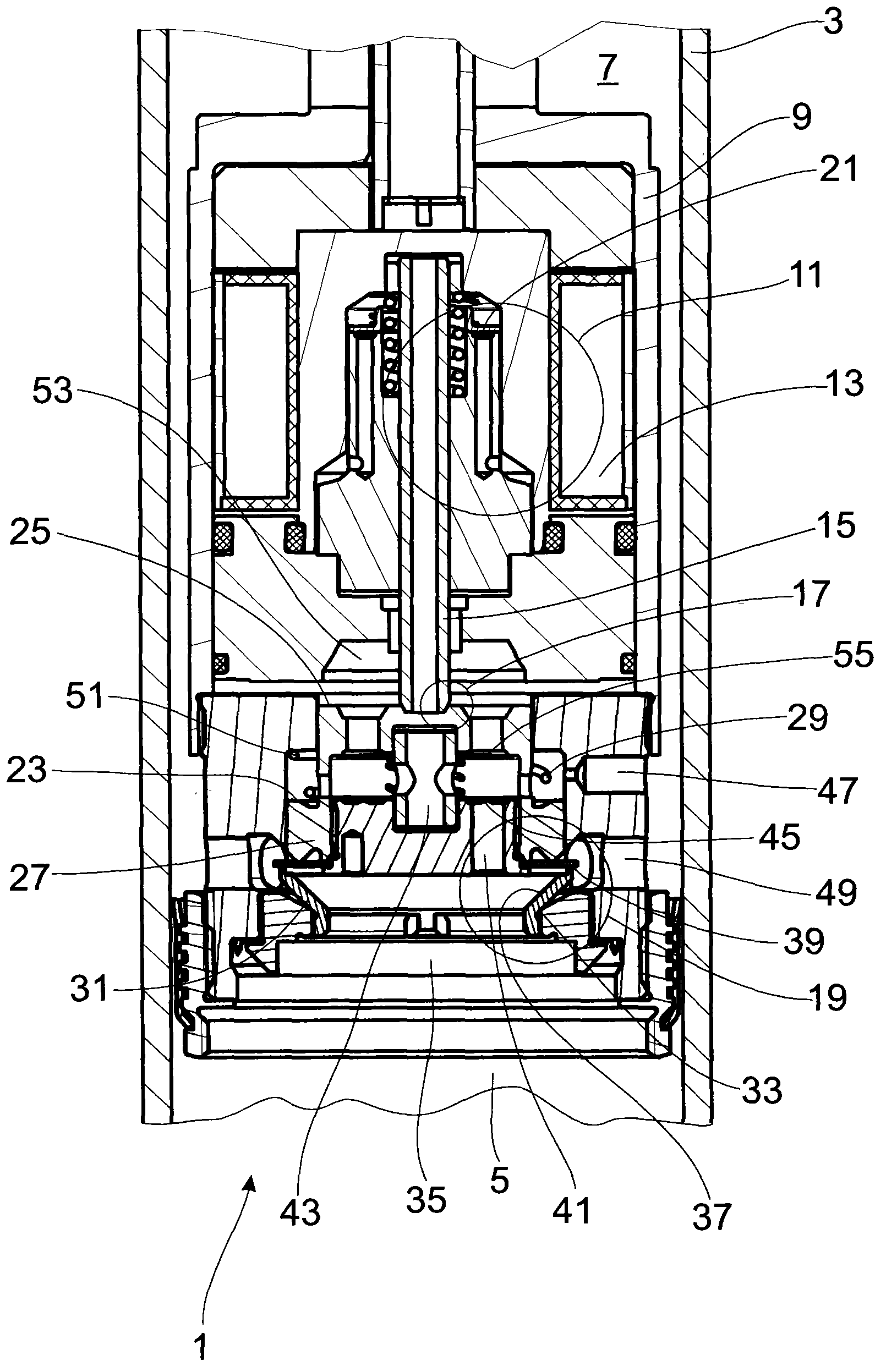
[0024] figure 1 A damping valve arrangement 1 for a shock absorber of any design is shown. The damping valve arrangement 1 can be arranged both within the cylinder 3 of the shock absorber between the two working chambers 5 ; 7 and also outside the cylinder 3 in a bypass line. Arranged in the damping valve housing 9 is an actuator 11 , which in this example comprises a solenoid coil 13 which exerts an axial actuating force on an axially movable pilot valve body 15 of a pilot valve 17 . The closing force on the main stage valve 19 can be influenced via the pilot valve 17 . This closing force is determined by the force of at least one valve spring 21 and the adjustment force of the actuator 11 acting against the valve spring force as well as the hydraulic closing force, which is controlled by the rigid main stage valve body 27 The pressure of the at least one pressure-loaded surface 23; 25 of .

[0025] The main-stage valve body 27 is additionally prestressed by a main-stage ...


PUM


Abstract

An adjustable damping valve arrangement comprises an actuator for controlling a main stage valve, wherein the main stage valve has a rigid main stage valve body which carries out an axial operating movement relative to a valve seat surface of the main stage valve. A pre-opening valve having at least one spring element which in turn preloads a pre-opening valve body precedes the main stage valve body. The main stage valve body is supported on the valve seat surface in the closed operating position by the pre-opening valve.

Description

technical field [0001] The invention relates to an adjustable damping valve arrangement according to the preamble of claim 1 . Background technique [0002] An adjustable damping valve arrangement is known from DE 10 2008 041 735 B3, in which the main-stage valve can be actuated by means of a pilot valve. The main stage valve includes a rigid main stage valve body seated on a seat ring. When flowing through the main-stage valve body through the through-opening, the main-stage valve body is lifted from the valve seat ring, so that the damping medium can flow through the damping valve arrangement. [0003] During the reverse flow of the damping valve arrangement through the at least one radial bore, the valve seat ring lifts together with the main-stage valve body from the housing-side seat surface. [0004] Under certain conditions, impact noises occur in the damping valve arrangement, which are at least jointly caused by the valve seat ring. One measure for noise reductio...

Claims


Application Information

Patent Timeline
Patent Type & Authority Applications(China)
IPC IPC(8): F16F9/34
CPCF16F9/464F16F9/465F16F9/46
Inventor T·曼格A·绍尔布赖
Owner ZF FRIEDRICHSHAFEN AG
Why Eureka
Try Eureka