
A hydraulically driven high-pressure grouting pump

A high-pressure grouting pump, hydraulic technology, used in pumps, piston pumps, machines/engines, etc., can solve the problems of high noise, high failure rate, short service life, etc. Effect

Active Publication Date: 2019-12-31
高军
View PDF6 Cites 0 Cited by
  • Summary
  • Abstract
  • Description
  • Claims
  • Application Information

AI Technical Summary

Problems solved by technology

Hydraulic grouting pumps are widely used in underground water blocking and reinforcement in coal mines. However, for the special environment of coal mines, due to safety considerations, solenoid valves are not suitable for reversing oil cylinders. At present, manual reversing valves are basically used to transform them into machine-controlled valves. A complex linkage mechanism is required, and because the hydraulic cylinder needs to move the mechanical control valve back and forth, the failure rate is high, the noise is large, and the service life is short

Method used


Image

  • A hydraulically driven high-pressure grouting pump
  • A hydraulically driven high-pressure grouting pump
  • A hydraulically driven high-pressure grouting pump

Examples


Embodiment Construction

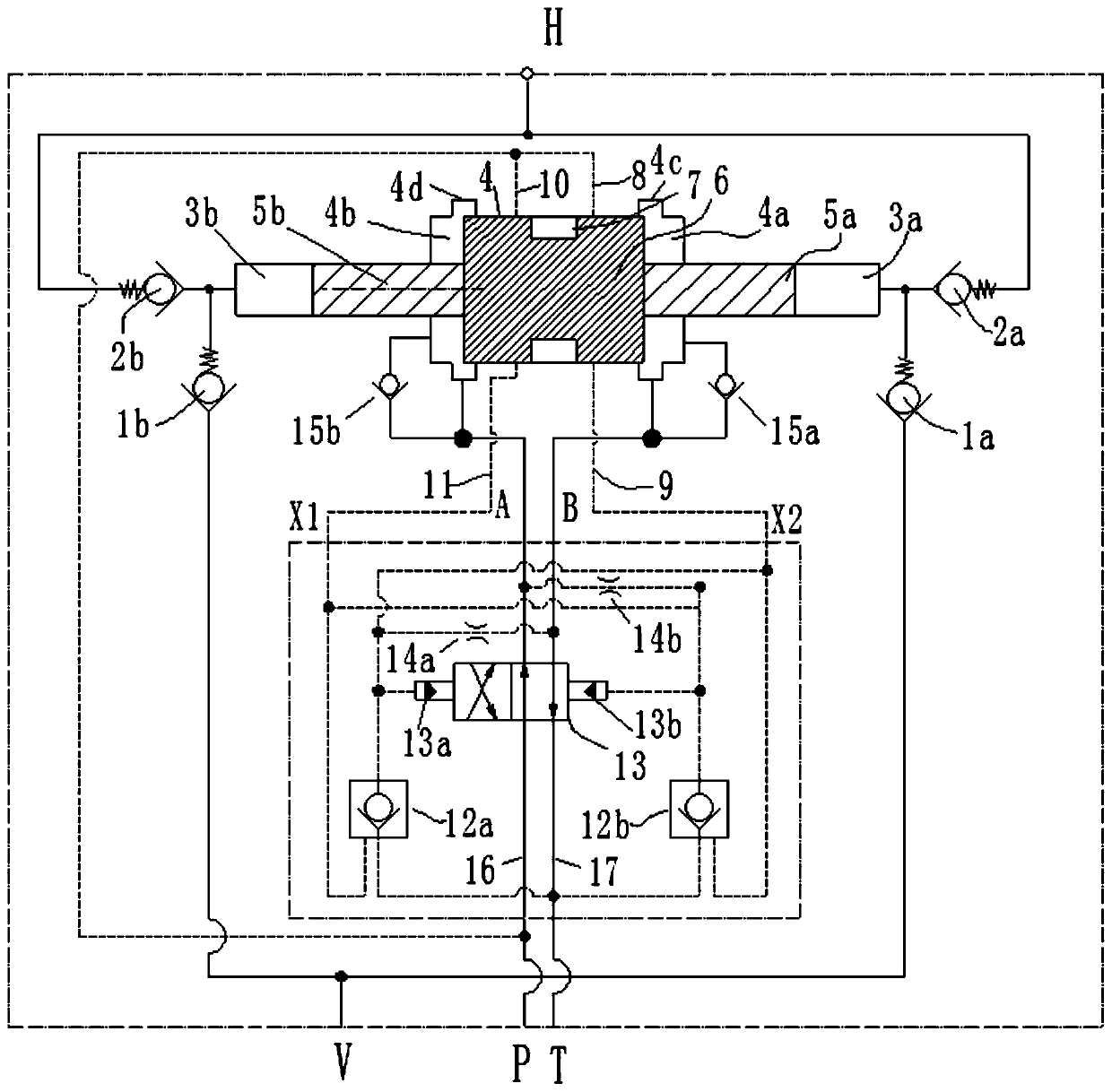
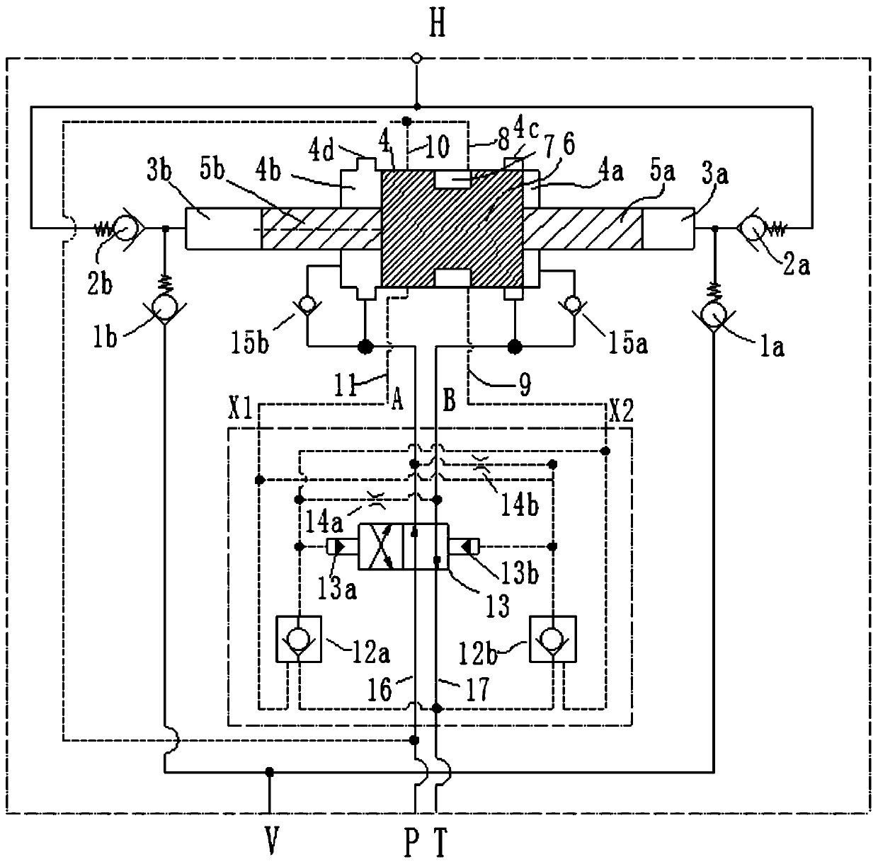
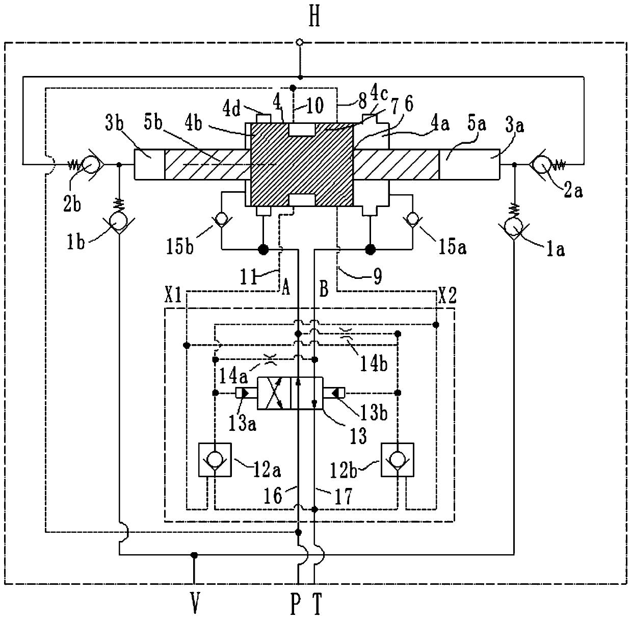
[0022] see Figure 1-3, as a preferred embodiment of the present invention, the present invention provides a hydraulically driven high-pressure grouting pump, which is provided with an oil inlet P, an oil return port T, a slurry inlet V, and a high-pressure slurry outlet H, which includes a pressurized Cylinder and hydraulic control reversing valve assembly; booster cylinder includes low-pressure cylinder 4, low-pressure piston 6, left high-pressure plunger 5b, right high-pressure plunger 5a, left high-pressure cylinder 3b and right high-pressure cylinder 3a, and low-pressure piston 6 is slidably set at low pressure In the cylinder 4, a left piston chamber 4b and a right piston chamber 4a are respectively formed at its left and right ends, and its left and right ends are respectively slidably arranged with the left high pressure plunger 5b in the left high pressure cylinder 3b and the right piston chamber 4a in the right high pressure cylinder 3a. The high-pressure plunger 5a ...


PUM


Abstract

The invention discloses a hydraulic-driven high-pressure grouting pump. The pump is provided with an oil inlet P, an oil return port T, a slurry inlet V and a high-pressure slurry outlet H, and comprises a pressurization cylinder and a hydraulic control reversing valve assembly; the pressurization cylinder comprises a low-pressure cylinder, a low-pressure piston, a left high-pressure plunger, a right high-pressure plunger, a left high-pressure cylinder and a right high-pressure cylinder, wherein the low-pressure cylinder is provided with a first oil inlet flow channel, a second oil inlet flowchannel, a first control flow channel and a second control flow channel, and an annular communication groove is formed in the low-pressure piston; when the low-pressure piston moves leftwards to the position where the low-pressure piston covers a first through-flow groove completely, the communication groove is used for communicating the first oil inlet flow channel with the first control flow channel to control reversing of the hydraulic control reversing valve assembly, and the low-pressure piston is braked through a closed left piston cavity; and when the low-pressure piston moves rightwards to the position where the low-pressure piston covers the second through-flow groove completely, the communication groove is used for communicating the second oil inlet flow channel with the second control flow channel to control reversing of the hydraulic control reversing valve assembly, and the low-pressure piston is braked through a closed right piston cavity. The high-pressure grouting pumpis simple in structure, electric control is not needed, and the low noise is achieved.

Description

technical field [0001] The invention relates to the technical field of grouting pumps, in particular to a hydraulically driven high-pressure grouting pump. Background technique [0002] At present, in the basic construction projects of mines, shafts and tunnels, various types of foundations, foundation pit reinforcement and slope protection construction of geotechnical engineering, reinforcement of various types of underground excavation tunnels and prevention of water, buildings and structures Settlement and Constructions such as inclined directional elevation and deviation correction are all carried out by grouting pumps to realize grouting, water blocking and backfilling, which not only improves the construction speed, but also improves the construction quality. However, the grouting pumps used in the past mostly adopt the crank connecting rod structure, and the grouting pumps with this structure are complicated in structure, large in volume and high in cost. [0003] In...

Claims


Application Information

Patent Timeline
Patent Type & Authority Patents(China)
IPC IPC(8): F04B15/02F04B9/113
CPCF04B9/113F04B15/02
Inventor 高军林晓谭发刚黎建华杨立云邵玉刚
Owner 高军
Learn More