Eureka AIR delivers breakthrough ideas for toughest innovation challenges, trusted by R&D personnel around the world.

Spiral conveying equipment

A technology of screw conveying and screw conveyor, which is applied in the field of screw conveying equipment, can solve the problems of staggered discharge port congestion and other problems, and achieve the effect of reducing space occupation, simple overall layout design process, and effective saving of layout space.

Active Publication Date: 2014-01-22
XUZHOU XCMG CONSTR MACHINERY CO LTD BUILDING MACHINERY
View PDF7 Cites 2 Cited by
  • Summary
  • Abstract
  • Description
  • Claims
  • Application Information

AI Technical Summary

Problems solved by technology

[0004] One of the objectives of the present invention is to propose a screw conveying device, which solves the problems of staggering, interference and congestion at the outlet when the screw conveyors are arranged in a centralized manner in the prior art

Method used


Image

  • Spiral conveying equipment
  • Spiral conveying equipment
  • Spiral conveying equipment

Examples


Embodiment Construction

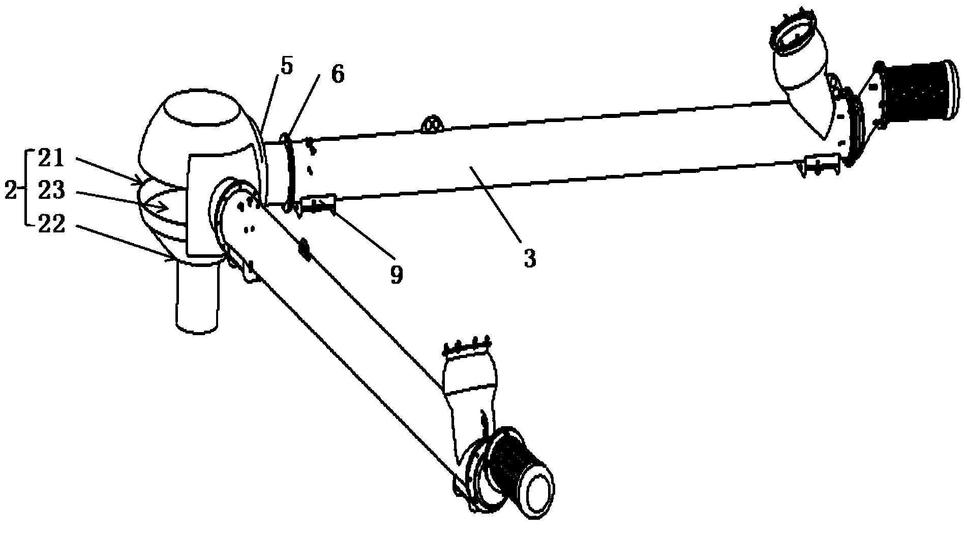
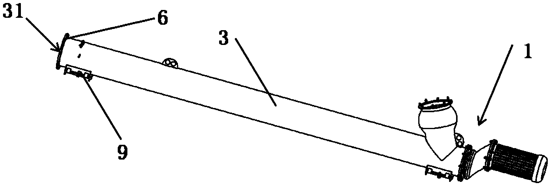
[0036] Below you can refer to the accompanying drawings Figure 1 to Figure 7 And the content of the text to understand the content of the present invention and the differences between the present invention and the prior art. The technical solution (including the preferred technical solution) of the present invention will be further described in detail below by way of the accompanying drawings and listing some optional embodiments of the present invention. It should be noted that: any technical feature and any technical solution in this embodiment are one or more of a variety of optional technical features or optional technical solutions. All the alternative technical features and alternative technical solutions of the present invention are cited, and it is not convenient for the implementation of each technical feature to emphasize that it is one of the optional multiple implementation modes, so those skilled in the art should know: Any technical features and any technical s...


PUM


Abstract

The invention discloses spiral conveying equipment, and relates to the technical field of engineering machines. The spiral conveying equipment is used for solving the problem that when spiral conveyors are arranged in a concentrated mode in the prior art, staggering, interference and material discharging outlet blocking occurring during conveying in a concentrated mode occur. The spiral conveying equipment comprises a concentrating head and at least two spiral conveyors. The concentrating head is provided with a cavity, an opening and a concentrated material discharging outlet, wherein the opening and the concentrated material discharging outlet are both communicated with the cavity, and the opening is formed above the concentrated material discharging outlet. Each spiral conveyor is provided with a material feeding pipe, wherein each material feeding pipe is provided with a material discharging port, and each material discharging port is communicated with the opening through a detachable connection structure. According to the spiral conveying equipment, a material discharging head of an existing spiral conveyor is eliminated, the spiral conveying equipment is provided with the concentrating head which is provided with the concentrated material discharging outlet, and the problem that when the spiral conveyors are arranged in a concentrated mode, staggering, interference and material discharging outlet blocking occurring during conveying in a concentrated mode occur can be solved.

Description

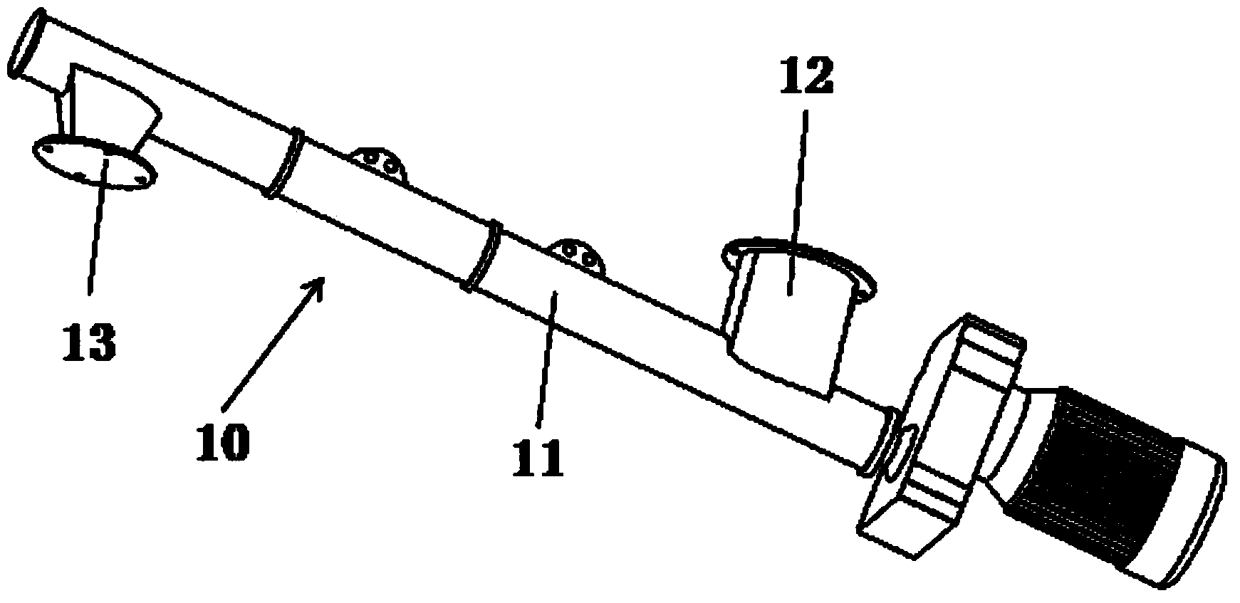
technical field [0001] The invention relates to the technical field of engineering machinery, in particular to a screw conveying device. Background technique [0002] At present, in the overall layout of conveyor application structures such as concrete mixing plants and dry-mixed mortar mixing plants, the utilization of internal space has always been an important issue. see figure 1 , in actual production, there are many applications where multiple screw conveyors 10 are used to centrally transport materials to one place. How to arrange the screw conveyor 10 flexibly and conveniently is an urgent problem to be solved. The existing screw conveyor 10 includes a feed pipe 11 on which a feed head 12 and a discharge head 13 are arranged. [0003] There are at least the following problems in the prior art: since the screw conveyor 10 needs a series of installation measures such as fixing and connecting to ensure normal operation, when the screw conveyor 10 is arranged in a cent...

Claims


Application Information

Patent Timeline
Patent Type & Authority Applications(China)
IPC IPC(8): B65G37/00
Inventor 于明勇马玉华张波郭铁坤张文强杨绵余秀华
Owner XUZHOU XCMG CONSTR MACHINERY CO LTD BUILDING MACHINERY
Why Eureka
Eureka Blog
Learn More