Passive type power vibration reduction floating slab track structure

A technology of dynamic vibration reduction and floating slabs, which is applied in the direction of tracks, roads, ballast layers, etc., can solve the problems of reducing the rigidity of track structures, affecting the life of equipment, and failing to reduce the impact of vibration, so as to reduce low-frequency vibration components and eliminate Effects of Harmful Vibrations

Active Publication Date: 2015-05-27
CHINA RAILWAY ERYUAN ENG GRP CO LTD
View PDF6 Cites 0 Cited by
  • Summary
  • Abstract
  • Description
  • Claims
  • Application Information

AI Technical Summary

Problems solved by technology

Due to the limit and cost of railway infrastructure, the increase in the mass of the track slab, which is one of the key components of the track structure, has a limited vibration damping effect; if the stiffness of the track structure is reduced, the natural frequency can be reduced, but the stiffness is too large. The displacement of the track structure will increase, which will bring hidden dangers to the safety of train operation. Therefore, it is no longer possible to further reduce the impact of vibration in the low-frequency range through the above-mentioned forms.
[0004] When the subway train passes through buildings with high vibration reduction requirements, such as scientific research institutions, concert halls, hospitals, military facilities, museums and ancient buildings, the low-frequency vibration components not only easily cause fatigue damage to the structure, affect the life of the equipment, but also affect The operating environment of properties such as museums above the railway and the working accuracy of precision instruments and meters along the line can easily lead to the failure of electrical components and automatic control systems. At the same time, vibration will inevitably generate noise, which will affect the work and physical and mental health of surrounding personnel.

Method used


Image

  • Passive type power vibration reduction floating slab track structure
  • Passive type power vibration reduction floating slab track structure
  • Passive type power vibration reduction floating slab track structure

Examples


Embodiment 1

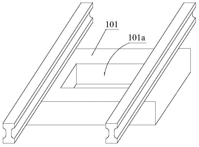
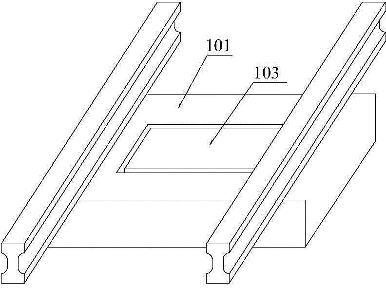
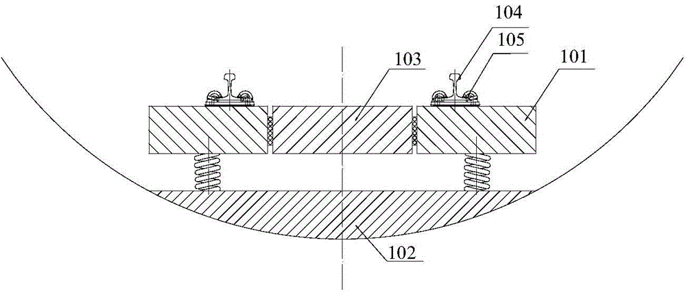
[0021] Embodiment 1: as figure 2 and image 3 As shown, an integral additional mass 103 is disposed in the frame space 101a of the floating plate main body 101, and an elastic connection is formed between the outer wall of the additional mass 103 and the side wall of the central cavity 101a through an elastic member.

Embodiment 2

[0022] Embodiment 2: as Figure 4 As shown, an integral additional mass 103 is disposed in the frame space 101 a of the floating plate main body 101 , and an elastic connection is formed between the bottom wall of the additional mass 103 and the surface of the supporting foundation 102 through an elastic member.

Embodiment 3

[0023] Embodiment 3: as Figure 5 As shown, the additional mass block 103 composed of multiple unit blocks is arranged in the frame space 101a of the floating plate main body 101, and the bottom wall of each unit block and the surface of the supporting base 102 are elastically connected by elastic members. . The additional mass 103 can either be embedded in the support base 106 or attached to the surface of the support base 106 .


PUM


Abstract

Provided is a passive type power vibration reduction floating slab track structure. Vibration components close to inherent frequency of the track structure are reduced, and harmful vibration of the track structure at a frequency band is eliminated. The passive type power vibration reduction floating slab track structure comprises floating slab main bodies (101), a supporting base (102) and steel rails (104). The steel rails (104) are fixed on the floating slab main bodies (101) through fasteners (105), and the floating slab main bodies (101) laid continuously along a line are placed on the supporting base (102) through vibration reducers (106). At least one additional mass block (103) is arranged within the length range of every floating slab main body (101) and elastically connected with the corresponding floating slab main body (101) or the supporting base (102) through elastic components.

Description

technical field [0001] The invention relates to a railway track structure, in particular to a floating slab track structure for passive dynamic vibration reduction. Background technique [0002] The floating slab track, also known as the mass-spring track system, is to place a concrete track bed slab with a certain mass and stiffness on the foundation through a shock absorber (steel spring or rubber shock absorber), and use the mass of the track bed slab Inertial forces are used to balance the dynamic loads caused by train operation. Since it was first applied in Germany in 1965, it has been widely used in urban rail transit at home and abroad because of its excellent vibration reduction performance. [0003] At present, the track structure with the best shock absorption effect is the steel spring floating slab track structure, and the first-order natural frequency of the existing floating slab track structure is about 12Hz, and the frequency that needs to be isolated in re...

Claims


Application Information

Patent Timeline
Patent Type & Authority Patents(China)
IPC IPC(8): E01B1/00E01B19/00
Inventor 杨吉忠颜华杨捷郑小艳潘自立林红松张雷蔡文峰傅丽霖和振兴徐志胜韩义涛
Owner CHINA RAILWAY ERYUAN ENG GRP CO LTD
Why Eureka
Try Eureka