Permanent magnet dual-clutch driving device used for railway diesel locomotive

A technology for internal combustion locomotives and driving devices, applied in the direction of magnetic drive clutches, non-mechanical drive clutches, clutches, etc., can solve the problems of frequent replacement of friction plates, low transmission efficiency, long service life, etc., and achieve controllable torque adjustment Guarantee, eliminate harmful vibration and wear, long service life effect

Active Publication Date: 2018-01-19
BAOJI TAIHUA MAGNETIC ELECTROMECHANICAL TECH RES INST CO LTD
View PDF14 Cites 0 Cited by
  • Summary
  • Abstract
  • Description
  • Claims
  • Application Information

AI Technical Summary

Problems solved by technology

[0003] The technical problem solved by the present invention is to provide a permanent magnet dual-clutch driving device for railway diesel locomotives. Low torque converter transmission efficiency, power interruption, low transmission efficiency and frequent replacement of friction plates when manual transmission clutch shifts, improve the transmission efficiency of automatic transmission locomotives, realize power uninterrupted shifting, reduce energy loss, and greatly eliminate Harmful vibration and wear are avoided, the life of the transmission is extended, and the damage caused by overload is avoided through the overload slip protection, and the service life is long. Using the air source on the locomotive to execute the device action, the structure is simple, easy to operate, and the torque adjustment and controllability are greatly guaranteed.

Method used


Image

  • Permanent magnet dual-clutch driving device used for railway diesel locomotive
  • Permanent magnet dual-clutch driving device used for railway diesel locomotive

Examples


Embodiment Construction

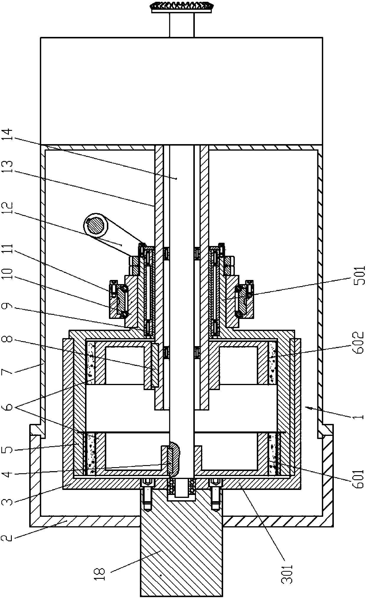
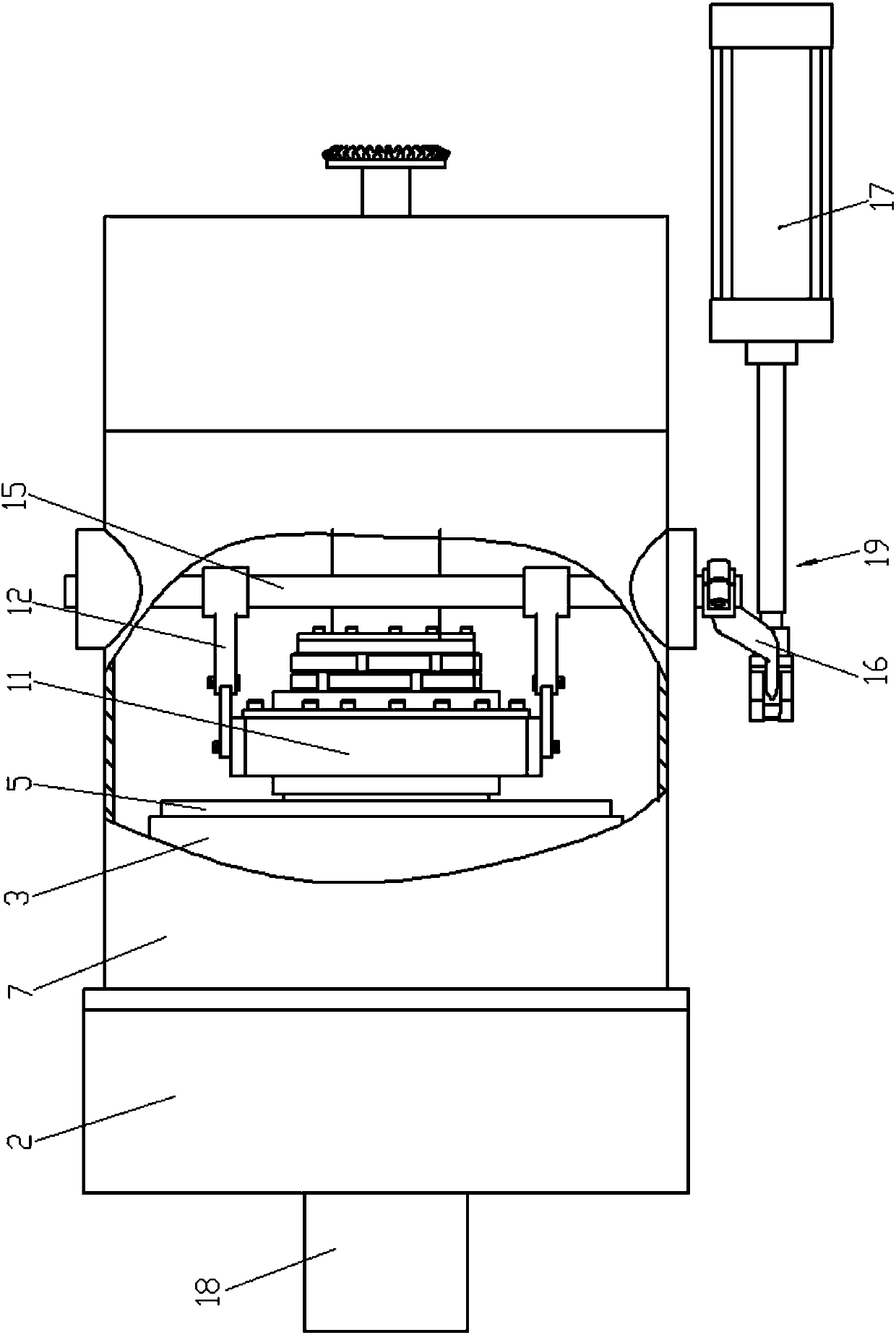
[0016] Attached below Figure 1-2 Embodiments of the present invention are described.

[0017] Permanent magnet dual clutch drives for railway diesel locomotives, such as figure 1 As shown, there is a permanent magnet two-way torque converter clutch device 1 , which includes a component assembly 3 , an outer rotor 5 , a magnetic inner rotor 6 , an output shaft 14 and a hollow output shaft 13 . The flywheel assembly 3 is a cylindrical structure, and the flywheel assembly 3 is fixedly connected to the output end of the crankshaft 18 of the engine. One end of the cylindrical structure of the flywheel assembly 3 is provided with a cylinder 301, and a bolt hole is processed on the cylinder 301. The cylinder body 301 of the flywheel assembly 3 is fixedly connected with the engine crankshaft 18 through bolts. The outer rotor 5 is a cylindrical structure with a hub 501, and the cylindrical outer surface of the outer rotor 5 is fixedly connected to the cylindrical inner surface of th...


PUM


Abstract

Disclosed is a permanent magnet dual-clutch driving device used for a railway diesel locomotive. The permanent magnet dual-clutch driving device is provided with a permanent magnetic bidirectional torque clutch device. The permanent magnetic bidirectional torque clutch device comprises a flywheel assembly, an outer rotor, a magnetic inner rotor, an output shaft and a hollow output shaft. The flywheel assembly is fixedly connected with an engine crankshaft. The outer rotor is axially, movably and fixedly connected with the flywheel assembly. The hollow output shaft is rotationally supported inan inner cavity of an outer rotor hub. The output shaft is rotationally supported in an inner cavity of the hollow output shaft. The magnetic inner rotor comprises a left inner rotor and a right innerrotor. One end of the hollow output shaft extends out of a hub and placed in an outer rotor cylinder, and the outer rotor cylinder is fixedly provided with the right inner rotor. One end of the output shaft extends out of the inner cavity of the hollow output shaft and rotationally supported in the engine crankshaft, and the engine crankshaft is fixedly provided with the left inner rotor. The exterior of an outer rotor hub is rotationally connected with a bearing seat. The bearing seat is connected with a locomotive gas source through a pneumatic driving device. By means of the permanent magnet dual-clutch driving device, the clutch device can be better controlled to adjust torque, the transfer efficiency is improved, power uninterrupted shifting is achieved, energy loss is reduced, harmful vibration wear is eliminated, and the permanent magnet dual-clutch driving device is simple in structure and easy to operate.

Description

technical field [0001] The invention belongs to the technical field of clutch devices for railway locomotives, and in particular relates to a permanent magnet dual-clutch driving device for railway diesel locomotives. Background technique [0002] The transmission system of railway diesel locomotive is mainly composed of mechanical transmission system, hydraulic transmission system and electric transmission system. The internal combustion engine is used as the driving force of the diesel locomotive, and the power is transmitted to the gearbox, The universal transmission device is transmitted to the drive axle to drive the wheels. The transmission system of railway diesel locomotives is mainly mechanical transmission system and hydraulic transmission system, and their power transmission components are mainly clutches and hydraulic torque converters. The clutch is an important part that connects the engine and the entire chassis system of the car. It is located between the en...

Claims


Application Information

Patent Timeline
Patent Type & Authority Applications(China)
IPC IPC(8): F16D27/01
Inventor 赵克中张新龙孙婷曾芬李成军
Owner BAOJI TAIHUA MAGNETIC ELECTROMECHANICAL TECH RES INST CO LTD
Why Eureka
Try Eureka