
Tandem type vacuum generator

A vacuum generator, series technology, applied in the direction of non-volume pumps, machines/engines, mechanical equipment, etc., can solve the problem of large consumption of compressed air, achieve the effect of shortening the arrival time and improving the rapidity of adsorption

Inactive Publication Date: 2014-01-22
SUZHOU SUPERLIGHT MICROELECTRONICS
View PDF0 Cites 8 Cited by
  • Summary
  • Abstract
  • Description
  • Claims
  • Application Information

AI Technical Summary

Problems solved by technology

However, in the prior art, a large-displacement vacuum generator is generally used when handling a workpiece with a fast beat and heavy weight, but this vacuum generator consumes a lot of compressed air

Method used


Image

  • Tandem type vacuum generator
  • Tandem type vacuum generator

Examples


Embodiment Construction

[0014] The present invention will be specifically introduced below in conjunction with the accompanying drawings and specific embodiments.

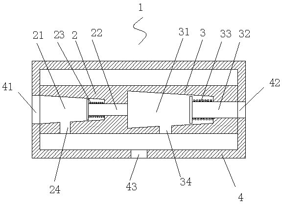
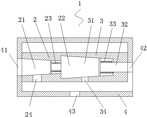
[0015] Such as figure 1 The shown series vacuum generator 1 includes at least two groups of vacuum generators, two groups in this embodiment, a vacuum generator 2 and a vacuum generator 3. The vacuum generator includes a nozzle and an expansion tube. There is a vacuum port, the nozzle 22 of the vacuum generator 2 is connected with the expansion tube 31 of the vacuum generator 3 to form a series connection, and they are jointly arranged in the vacuum generator housing 4 . In another preferred embodiment, the nozzle 22 of the vacuum generator 2 is the expansion tube 31 of the vacuum generator 3 . The nozzles and expansion tubes of the vacuum generator 2 and the vacuum generator 3 have different sizes, and the sizes increase sequentially from the compressed air inlet 41 to the compressed air outlet 42 . There is a one-way valve at the conn...


PUM


Abstract

The invention relates to a vacuum generator, in particular to a tandem type vacuum generator. The tandem type vacuum generator comprises at least two sets of vacuum generator bodies and a vacuum generator outer shell. Each vacuum generator body comprises a nozzle and an expansion tube, and a vacuum opening is formed in each expansion tube. According to the at least two sets of vacuum generator bodies, the nozzle of the previous vacuum generator body is connected with the expansion tube of the next vacuum generator body to form serial connection, and the at least two sets of vacuum generator bodies are together arranged in the vacuum generator outer shell. The vacuum generator outer shell comprises a compressed air inlet, a compressed air outlet and a vacuum opening, and compressed air enters the tandem type vacuum generator from the compressed air inlet of the vacuum generator outer shell, sequentially passes through the at least two sets of vacuum generator bodies and is discharged from the compressed air outlet of the vacuum generator outer shell. Multiple vacuum generator bodies are connected in series, the energy of the compressed air discharged from the previous vacuum generator body is recycled, and therefore the time for achieving vacuum is shortened, and the sorption rapidity of the vacuum generator is improved.

Description

technical field [0001] The invention relates to a vacuum generator, in particular to a serial vacuum generator. Background technique [0002] The traditional vacuum generating device uses a vacuum pump to convert electrical energy into mechanical energy, which drives the rotating blades to rotate at a high speed, so that the discharge and suction of air are accelerated to form a vacuum. However, this kind of vacuum device is large in size, heavy in weight, loud in noise and high in energy consumption, and gradually cannot meet the increasingly high requirements of some precision manufacturing industries. Therefore, a vacuum generator that uses compressed air to generate vacuum is small in size, The characteristics of light weight, high vacuum degree and fast response replace the traditional vacuum generating device. This kind of vacuum generator is often used in electronics, chemical industry, construction, food and other industries, and plays the role of vacuum adsorption ...

Claims


Application Information

Patent Timeline
Patent Type & Authority Applications(China)
IPC IPC(8): F04F5/22
Inventor 乔金彪
Owner SUZHOU SUPERLIGHT MICROELECTRONICS
Learn More