Processing box

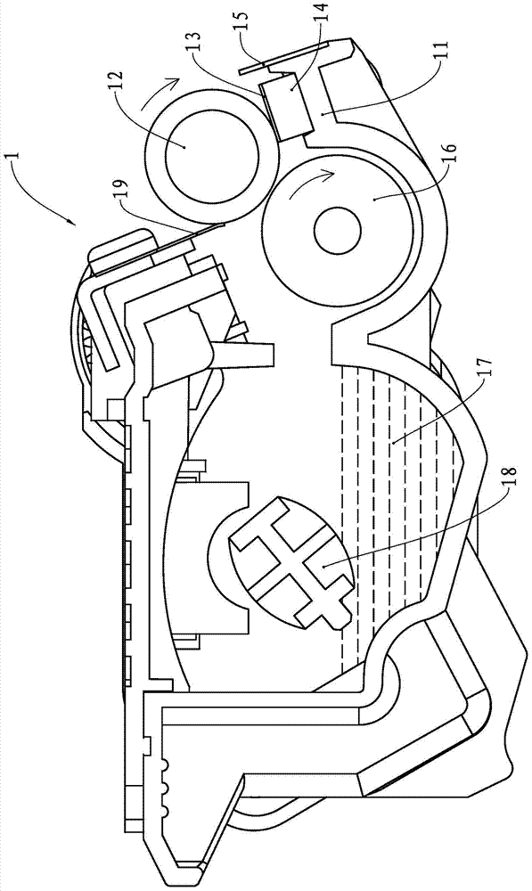
A technology for processing cartridges and consumables, applied in the field of processing cartridges, can solve the problems that the sealing blade 13 cannot be in close contact with the developing roller 12, the contact surface gap between the sealing blade 13 and the developing roller 12, and the sealing is not strict.

Active Publication Date: 2014-01-22
PRINT RITE UNICORN IMAGE PROD CO LTD
View PDF5 Cites 3 Cited by
  • Summary
  • Abstract
  • Description
  • Claims
  • Application Information

AI Technical Summary

Problems solved by technology

[0006] Since the sealing blade 13 is in contact with the tangent surface of the developing roller 12, when the sealing blade 13 is slightly deformed, a gap will appear on the contact surface between the sealing blade 13 and the developing roller 12, resulting in a loose seal, resulting in ...

Method used


Image

  • Processing box
  • Processing box
  • Processing box

Examples


Embodiment Construction

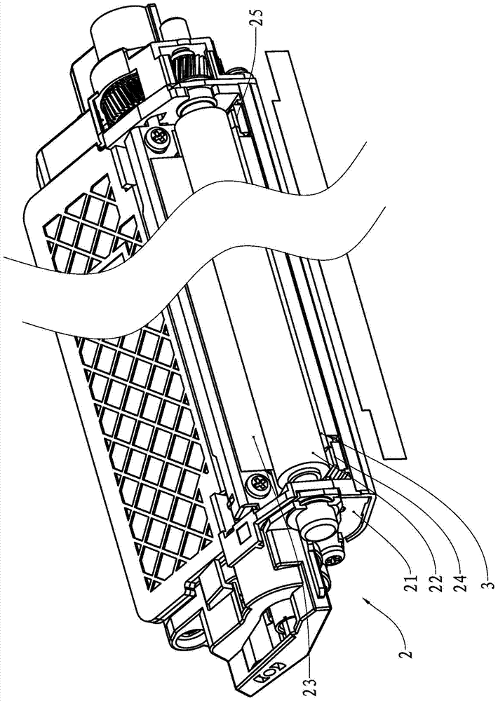
[0033] Reference image 3 , image 3 It is a structural diagram of the processing box 2 of the present invention. The processing box 2 includes a housing 21. On one end of the housing 21, a powder outlet knife 23, a sealing felt 24, a sealing felt 25, and a sealing assembly are provided. The sealing assembly includes a sealing blade 3 And seal 4 ( Figure 5 visible). The housing 21 encloses a cavity containing toner as a printing consumable. One end of the cavity is provided with a toner outlet. The toner outlet is surrounded by a powder ejection knife 23, a sealing felt 24, a sealing felt 25 and a sealing component. A developing roller 22 is installed at the toner outlet, and a sealing assembly is installed under the developing roller 22.

[0034] Reference Figure 4 , Figure 4 For the structure diagram of the sealing blade 3, the sealing blade 3 includes a fixed portion 31 and a contact portion 32. The angle formed between the fixed portion 31 and the contact portion 32 is α i...


PUM


Abstract

The invention provides a processing box. The processing box comprises a shell, a develop roller and a first sealing part. A cavity for containing supplies is defined by the shell, a supply outlet is formed in one end of the cavity, the develop roller is installed at the position, close to the supply outlet, inside the cavity and the first sealing part is installed below the develop roller and fixed onto the supply outlet. The processing box further comprises a sealing doctor blade, the sealing doctor blade comprises a fixed portion and a contacting portion, the fixed portion is fixed onto the supply outlet, the contacting portion comprises a first end portion and a contacting end face, the first end portion is connected with the first sealing part in abutting mode, and the contacting end face is elastically connected with the develop roller in an abutting mode. According to the processing box, the sealing doctor blade makes elastic contact with the develop roller, so that the sealing doctor blade is not prone to deforming, and improvement of the sealing performance and the durability of the processing box is facilitated.

Description

Technical field [0001] The present invention relates to a process box, and more specifically, to a process box equipped with a sealing blade. Background technique [0002] Image imaging equipment is a device that uses electrophotographic imaging principles to form images on recording materials. Image imaging equipment includes copiers, printers, and fax machines. The process cartridges used in image imaging equipment are generally divided into two types, one is an integrated process cartridge that includes a developing roller and a photosensitive drum as a developing device, and the other is a separate process cartridge that separates the photosensitive drum. Both types of process cartridges are detachably installed in the main body of the image imaging apparatus. [0003] A typical image imaging device is a laser printer. The laser printer is currently one of the most widely used image imaging devices. The laser printer uses the physical and chemical principles of light, electric...

Claims


Application Information

Patent Timeline
IPC IPC(8): G03G21/18
Inventor 范文燚杨晓锋
Owner PRINT RITE UNICORN IMAGE PROD CO LTD
Why Eureka
Try Eureka