
Clamping feeding mechanism for lace lamps

A lamp clip and feeding technology, applied in metal processing equipment, feeding devices, manufacturing tools, etc., can solve the problems of low efficiency, large error, insufficient punching accuracy, etc., and achieve good clamping and feeding effect.

Active Publication Date: 2014-01-29
德清县翔鹰金属制品有限公司
View PDF7 Cites 2 Cited by
  • Summary
  • Abstract
  • Description
  • Claims
  • Application Information

AI Technical Summary

Problems solved by technology

This kind of punching step has the following defects: one is that the manual operation is used to punch holes, and the efficiency is very low; the other is that the manual operation is not accurate enough to punch holes, and large errors will occur

Method used


Image

  • Clamping feeding mechanism for lace lamps

Examples


Embodiment Construction

[0010] Combine below figure 1 Specific description embodiment:

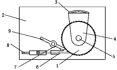
[0011] A lace lamp clamping and feeding mechanism, characterized in that the lace lamp clamping and feeding mechanism includes a toothed plate 1, the toothed plate 1 is movably hinged on the bracket 2, and the toothed plate 1 is fixed with The lower splint 3, the lower splint 3 is provided with an upper splint 4, the upper splint 4 can be clamped with the lower splint 3 through the cylinder 5, and the support 2 is provided with a push rod 6 and a rotation stop rod 7. One end of the push rod 6 is in contact with the chainring 1, and the other end of the push rod 6 is connected with a linkage rod 8. Under the action of the linkage rod 8, the push rod 6 can make the teeth The disk 1 rotates, and the front end of the anti-rotation rod 7 is engaged with the toothed disk 1 .

[0012] Preferably, a wrench 9 is connected to the rear end of the anti-rotation rod 7 .

[0013] The lace lamp clipping and feeding mechanism...


PUM


Abstract

The invention belongs to the technical field of lace lamp tools and particularly relates to a clamping feeding mechanism for lace lamps. The mechanism comprises a fluted disc which is movably hinged to a support, a lower clamping plate is fixed on the fluted disc, one end of a pushing rod is in contact with the fluted disc, the other end of the pushing rod is connected with a linkage rod, the pushing rod can drive the fluted disc to rotate under the action of the linkage rod, and the front end of a rotation stopping rod is snapped with the fluted disc. According to the mechanism, lace lamp parts can be well clamped and fed during perforation, and accordingly, the whole process automatic operation of clamping and feeding is achieved.

Description

technical field [0001] The invention belongs to the technical field of lace lamp appliances, in particular to a material clamping and feeding mechanism for lace lamps. Background technique [0002] The lace lamp will punch holes in its parts during the production process. The traditional method of punching the parts in the lace lamp is to manually operate the parts, place them under the punching machine, and then step on the switch of the punching machine to make the punching machine press down, and then press the lace lamp Parts are punched. After punching a hole, then move the lace lamp part to perform the second punching step, and punch holes in sequence. There are following defects in this type of punching step: one is that manual operation is used for punching, which is very inefficient; Contents of the invention [0003] The purpose of the present invention is to solve the technical problems described above, and to provide a lace lamp clamping and feeding mechanis...

Claims


Application Information

Patent Timeline
IPC IPC(8): B21D43/14B21D43/00B21D28/24
Inventor 沈昌荣
Owner 德清县翔鹰金属制品有限公司
Learn More